
RF connector reliability: Datasheet analysis for 3-1478924-1
Point: Field experience shows connector-related problems are a nontrivial source of RF link downtime; industry surveys commonly attribute roughly 15–20% of link incidents to connector or cable failures. Evidence: MTBF estimates vary widely depending on environmental exposure and mating practice. Explanation: This article gives a practical, stepwise datasheet analysis to evaluate RF connector reliability for part 3-1478924-1.
Point: The goal is actionable assessment. Evidence: Engineers need a checklist that maps datasheet entries to system risk and test steps they can run in-house or in pilot deployments. Explanation: The process below emphasizes extracting electrical, mechanical, and environmental entries from the datasheet and validating them against expected application stresses.
1 — Quick background: what “reliability” means for RF connectors (background introduction)
What reliability metrics engineers care about
Point: Reliability for RF connectors covers electrical stability and mechanical endurance. Evidence: Key metrics include MTBF/MTTF, contact resistance stability, insertion loss drift, VSWR consistency, rated mating cycles, operating temperature, humidity/vibration qualifications, and dominant failure modes. Explanation: Each metric maps to system impact — e.g., rising contact resistance increases loss, while VSWR drift reduces margin and can trigger amplifier faults.
How datasheets present reliability data
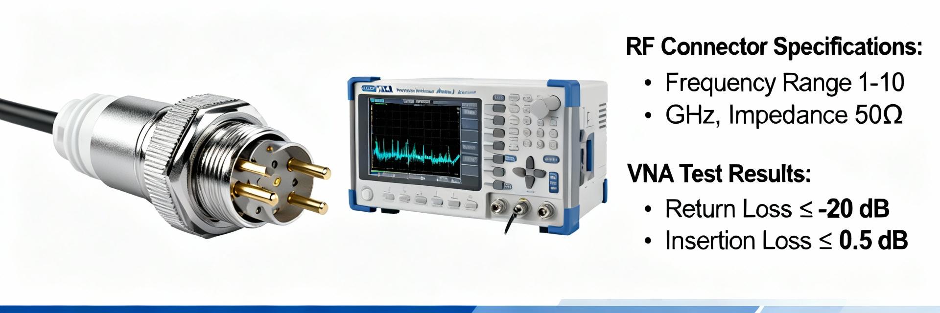
Point: Datasheets group electrical, mechanical, and environmental specs but vary in completeness. Evidence: Typical sections list contact resistance, insulation resistance, insertion loss/return loss tests, mating cycles, and environmental test conditions with brief method notes. Explanation: Careful reading is required because “typical” values, missing sample sizes, or unspecified test methods create ambiguity about field performance.
2 — Datasheet quick-read: locating critical reliability entries for 3-1478924-1 (data-analysis)
Must-check specs: electrical, mechanical, environmental
Point: Extract a concise set of fields from the datasheet for comparison. Evidence: Required entries include contact resistance, insulation resistance, insertion loss, return loss/VSWR, rated mating cycles, operating temperature range, shock & vibration, humidity/damp-heat, altitude, base materials, and plating. Explanation: For 3-1478924-1 use these fields to build pass/fail thresholds and to compare against system requirements.
| Field | Value (extract) |
|---|---|
| Contact resistance / Insertion loss / VSWR / Mating cycles / Temp range / Materials | — extract exact datasheet rows for 3-1478924-1 |
Red flags and ambiguous statements in datasheets
Point: Watch for missing methods or vague qualifiers. Evidence: Red flags are absent test methods, no sample size, “typical” only values, or unspecified frequency points for insertion loss/VSWR. Explanation: When 3-1478924-1 lacks detail, request full qualification reports or ISO-style test protocols to avoid hidden risk from lab-only conditions that don’t reflect field environments.
3 — Interpreting test data and limits: what the numbers really mean (data-analysis)
Translating electrical specs into operational risk
Point: Small dB changes materially affect link margin. Evidence: A 0.2 dB rise in insertion loss reduces margin and can force higher amplifier gain or increase BER in low-SNR links. Explanation: Convert datasheet delta insertion loss into dB margin loss, then estimate impact on BER or required amplifier headroom for the target frequency band and modulation.
| Mating cycles | Insertion loss (dB) |
|---|---|
| 0 | 0.10 |
| 500 | 0.12 |
| 1000 | 0.18 |
Interpreting mechanical & environmental test results
Point: Mechanical wear and environmental stress reveal likely failure modes. Evidence: Trends in contact resistance over cycles indicate fretting or plating wear; thermal cycling shows solder or dielectric degradation; vibration tests reveal mechanical loosening. Explanation: Map test severity to application class (telecom rack, industrial, airborne) and accept only those specs that match or exceed expected in-service stresses.
4 — Verification & test plan: how to validate 3-1478924-1 reliability claims (method/guide)
Benchmark test matrix to run in-house
Point: Run a compact, prioritized matrix. Evidence: Suggested tests: accelerated lifecycle (≥1000 mating cycles), insertion loss/VSWR vs. cycles, contact resistance trend, thermal cycling (−40°C to +85°C for industrial), shock & vibration per intended class, damp-heat. Explanation: Use sample sizes of 5–10 for initial qualification, set pass thresholds relative to datasheet max + engineering margin (e.g., insertion loss ≤ datasheet max +0.2 dB).
Lab vs. field validation: pilot installations and monitoring
Point: Complement lab tests with pilots. Evidence: Deploy 10–20 pilot connectors in representative systems, log S-parameters periodically, record temperature, RF power, and events. Explanation: Correlate lab trends with field drift; ensure fixtures and calibration prevent false positives (use torque-controlled mating, calibrated VNAs, and temperature chambers for repeatability).
5 — Design & selection checklist for system engineers (method/guide / case)
Matching connector specs to system requirements
Point: Apply a short decision matrix at selection. Evidence: Check frequency range & VSWR margin, power handling at operating temperature, rated mating cycles, environmental class, plating compatibility with cable and solder, and mechanical mounting constraints. Explanation: Quick-pass criteria: frequency cover and VSWR margin met, mating cycles ≥ expected life; deal-breakers include missing temperature rating or unspecified plating.
- Decision matrix: frequency match, VSWR margin ≥0.5 dB headroom, power derating factor, mating cycles ≥ design life, plating compatibility — prioritize items as pass/fail for procurement.
Risk mitigation options when datasheet margins are thin
Point: When datasheet margins are tight, apply mitigation. Evidence: Effective tactics include derating power, secondary environmental sealing, redundant paths, enhanced incoming inspection, and specifying higher-grade mating hardware. Explanation: These actions reduce the probability of in-service failure without delaying procurement; quantify residual risk in the component risk register.
6 — Practical recommendations & next steps for engineers evaluating 3-1478924-1 (action)
Immediate checklist before approval
Point: Execute a short prioritized list. Evidence: Actions: extract datasheet rows into a comparison table, request qualification reports for 3-1478924-1, run lifecycle insertion loss and contact resistance tests on samples, perform a small pilot, and update the risk register. Explanation: These steps rapidly expose gaps between datasheet claims and expected service conditions while keeping procurement on schedule.
When to reject or re-specify the connector
Point: Define clear rejection triggers. Evidence: Reject if key ratings are absent, pilot tests show unacceptable insertion loss or VSWR drift, mating cycles are below life requirements, or materials are incompatible. Explanation: Re-specify immediately when any of these occur; document failure modes and required thresholds to guide suppliers toward acceptable alternatives.
Summary
- Perform a focused datasheet extraction for 3-1478924-1 capturing contact resistance, insertion loss, VSWR, mating cycles, temp range, and materials; these fields drive RF connector reliability assessment and risk scoring.
- Translate electrical deltas into link-budget impacts: small dB increases can meaningfully reduce margin and require amplifier or modulation changes.
- Validate datasheet claims with a combined lab lifecycle matrix and a small field pilot to detect artifacts and environment-driven degradation.
- Use a pass/fail decision matrix in procurement and apply mitigation (derating, sealing, redundancy) when margins are thin to reduce in-service failures.
FAQ
How should I read insertion loss and VSWR entries on the datasheet for 3-1478924-1?
Point: Verify frequency point and test method. Evidence: Datasheet values should state test frequency, fixture, and max/typical distinction. Explanation: Use the max specification for acceptance thresholds; if only “typical” is given, request measured max values or run your own VNA sweep to establish conservative margins for your system.
What sample size is sufficient to validate mating-cycle claims?
Point: Use statistically meaningful samples for early qualification. Evidence: Start with 5–10 units for initial lab runs, expand to 20–50 if variation appears or for final acceptance. Explanation: Small samples show gross issues quickly; larger samples reduce uncertainty in wear-out distribution and support confidence before high-volume procurement.
Which environmental tests most correlate with field failures for RF connectors?
Point: Thermal cycling, vibration, and damp-heat are high-value tests. Evidence: Thermal cycling exposes material mismatches, vibration induces fretting, and damp-heat accelerates corrosion. Explanation: Prioritize tests that reflect your deployment environment, and ensure test severity aligns with application class to surface realistic failure mechanisms rather than lab-only artifacts.