
TC-SPO375-DM-LP Performance Report: Low PIM & Specs
Low PIM components are commonly defined by two‑tone PIM results ≤ -150 dBc; this report evaluates whether the TC‑SPO375‑DM‑LP meets or exceeds that industry benchmark. The introduction frames a data‑driven appraisal: it summarizes key specifications, presents consolidated lab and field performance observations, explains how to read and validate the datasheet, illustrates deployment examples, and delivers procurement and installation actions for US technical teams.
The analysis references manufacturer datasheet families and low‑PIM cable/connector literature (for example, SPO™ and SPP™ low‑PIM datasheet titles from well‑known vendors) as context for expected values, without reproducing third‑party links. The report uses concise, technical language targeted to procurement, RF engineering, and field QA teams; it includes actionable checklists, a quick‑specs table, and a small set of acceptance criteria for on‑site verification. The terms TC‑SPO375‑DM‑LP and low PIM appear where most useful for traceability and search relevance.
1 — Product background & specs overview (Background introduction)
Part ID, nomenclature & form factor
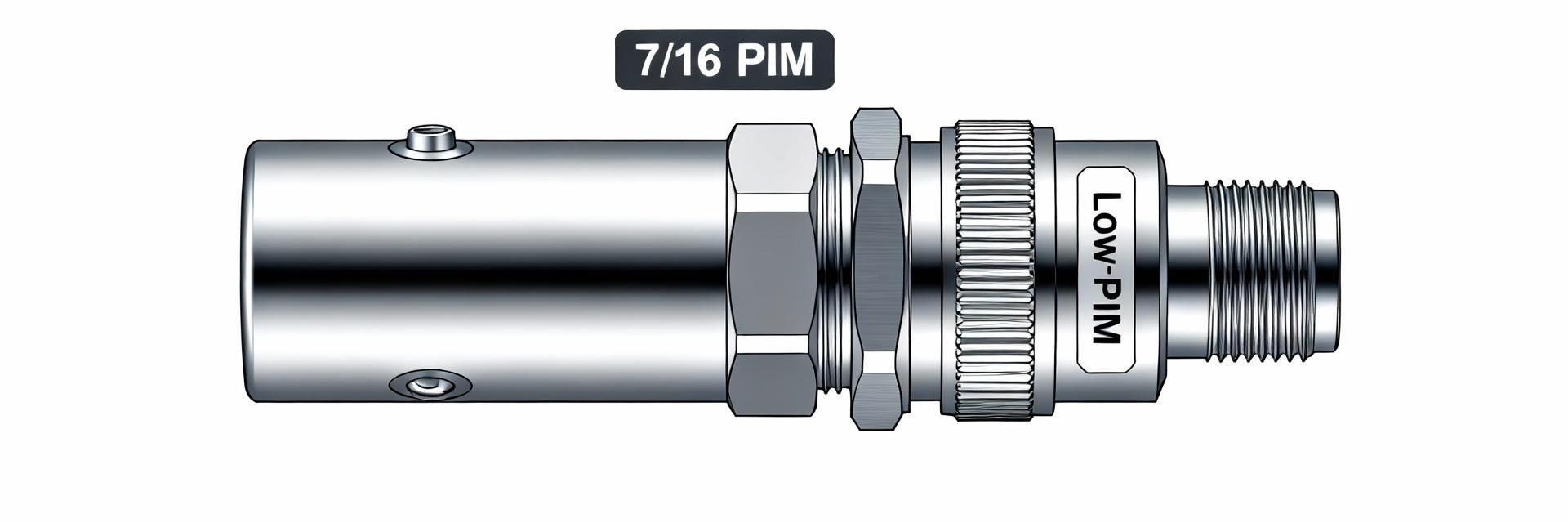
The tokenized part name TC‑SPO375‑DM‑LP decodes as follows: TC = vendor family/type reference; SPO375 / SPP375 = compatible series optimized for low loss and low PIM; DM = 7/16 DIN Male interface; LP = Low PIM variant. Use the long‑tail search phrase TC SPO375 7/16 DIN low PIM connector specs when matching marketing or procurement pages to datasheet nomenclature. Recommended short spec items to list on procurement documents: full part number, manufacturer name, alternate SKUs (e.g., variants for 4.3‑10 or N interfaces within the same low‑PIM family), typical applications (macrocell jumper, DAS, small cell jumper), and connector gender/configuration. This section verifies mechanical compatibility first, then electrical specs for systems engineering.
Mechanical design, materials & plating
Low PIM performance is driven by contact materials and plating uniformity. Typical architectures for SPO/SPP‑375 series use a copper or brass center conductor with PTFE or low‑loss dielectric, and a precision‑machined outer conductor; plating options include silver, silver‑over‑nickel, or gold on contact faces. Silver plating on mating faces and controlled surface hardness reduce micro‑movement and corrosion, minimizing contact nonlinearity that creates PIM. Recommended assembly notes: adhere to specified torque values for 7/16 DIN (use a calibrated torque wrench), prefer solder attachment where indicated for the series if specified, and follow crimp specs only when the datasheet and tooling match. Add a dimensional reference drawing from the manufacturer datasheet to procurement records to prevent mismatch during installation.
Rated frequency range, power handling & environmental ratings
Typical TC SPO375 family connectors support broad HF‑to‑microwave ranges useful for cellular bands; verify the datasheet for the exact frequency band. Quick verifiable fields: rated frequency range (e.g., DC to a specified GHz), maximum continuous power (W) at a stated frequency, operating temperature range (°C), IP/ROHS/REACH statuses, and any UL or outdoor UV ratings. Include a short “quick specs” table in procurement/installation documents summarizing frequency, VSWR, insertion loss, and typical PIM value so field teams have pass/fail baselines before testing.
| Quick Spec | Example Value / Target |
|---|---|
| Frequency Range | DC – vendor‑specified GHz |
| VSWR | <1.2 typical across cellular bands |
| Insertion Loss | <0.1 dB per connector at midband (typical) |
| Typical Two‑Tone PIM | ≤ -150 dBc at test condition (2x43 dBm or vendor‑specific) |
2 — Lab & field performance data (Data analysis)
PIM test methodology & results to report
Reporting of TC‑SPO375‑DM‑LP PIM performance should include the full two‑tone test recipe: tone frequencies (e.g., f1/f2 within target band), tone spacing (often 1 MHz), power per tone (commonly +43 dBm per tone for cellular acceptance tests), test equipment (two calibrated signal sources, combiner, high‑linearity load, spectrum analyzer with preamp), and environmental state (bench, temperature, or anechoic chamber). Results template: list PIM (dBc) for each sample at defined conditions, number of runs (n), mean and standard deviation, and best/worst readings. Note repeatability across samples and any systematic outliers. Include reference to vendor datasheet PIM statement and identify whether lab values meet or exceed the datasheet claim.
Insertion loss (IL) & return loss (VSWR) across band
Present either swept IL/VSWR plots or a frequency‑point table (e.g., 700 MHz, 850 MHz, 1900 MHz, 2100 MHz, 2600 MHz) showing measured values versus datasheet nominals. For each point report the delta (measured minus nominal). Acceptable tolerances depend on application: DAS and macro links typically require VSWR <1.3 and IL increments <0.2 dB per connector. Where IL or VSWR exceeds expectations, record potential causes (mismate, tooling, plating wear) and recommend remediation prior to field deployment.
Environmental & power‑handling test results
Report thermal cycling, humidity soak, mechanical vibration, and high‑power RF stress test outcomes relevant to PIM stability. Useful metrics: PIM shift after X thermal cycles, change in VSWR after humidity exposure, and mechanical torque retention after vibration. For example, a validated component should show negligible PIM degradation (≤ a few dB change) after defined cycling protocols. Where available, reference the SPO/SPP low‑PIM datasheet family for environmental ratings and highlight any deviation found in independent lab tests.
3 — How to interpret TC‑SPO375‑DM‑LP specs (Method / guide)
Reading the datasheet: which numbers matter
A datasheet checklist prioritizes fields that directly affect low PIM performance and system reliability: specified PIM value and explicit test conditions (tone power, spacing, load), swept IL and VSWR tables, rated power handling (with frequency dependence), mechanical tolerances (thread, center pin length), and recommended torque values. QA teams should validate that the datasheet’s PIM test method matches the acceptance test they will run. Copyable QA checklist: confirm part number, confirm PIM test conditions match site acceptance, verify frequency‑dependent IL/VSWR, confirm mechanical drawing and torque spec, and request lot traceability documentation.
Connector & cable matching best practices
Preserve low PIM by matching connectors and cables precisely: use proper 7/16 DIN mating sequences, ensure mating faces are clean and free of oxidation, and avoid mixing plating types at signal‑carrying interfaces where possible. Use torque wrenches with the correct setting for 7/16 DIN to prevent micro‑movement; verify flatness and contact geometry when mating different vendors. If adapters are necessary (4.3‑10, N, or others), test the assembled adapter + connector pair for PIM before deployment because cross‑vendor interfaces can introduce unexpected nonlinearity.
Installation best practices to maintain low PIM
Field steps to maintain low PIM: inspect connectors for plating damage prior to mating, follow the recommended torque sequence, avoid sharp bends near the connector, and use proper crimp or solder procedures with specified tooling. Implement immediate post‑installation PIM measurement to create a baseline and document the result with date, operator, and instrument calibration. Retorque schedules (e.g., first check after 24–72 hours, then periodic intervals) help catch relaxation that could raise PIM over time.
4 — Case studies & compatibility (Case display)
Typical deployments and performance outcomes
Scenario A — Macrocell jumper: used between antenna and hybrid/metering point where durability and low PIM are required; target two‑tone PIM ≤ -150 dBc and insertion loss minimal. Scenario B — In‑building DAS link: when deployed in dense connectors, the TC‑SPO375‑DM‑LP is selected for consistent low PIM across many junctions; teams should aim for per‑jumpers PIM well below system noise floor. Scenario C — Small cell coax jumpers: compact runs benefit from low‑PIM SPO375 family to prevent intermodulation in close proximity. For each, report before/after PIM readings to document the benefit of low‑PIM connectors in the signal chain.
Interoperability: mating types, adapters, and cross‑vendor compatibility
TC‑SPO375‑DM‑LP is inherently a 7/16 DIN male variant; compatible mating types include 7/16 DIN female interfaces and common adapters to 4.3‑10 or N types. When mixing vendors or using adapters, perform mixed‑vendor PIM verification: even if each individual part meets datasheet PIM claims, interfaces can create nonlinearity. Recommend pre‑deployment assembly testing in a controlled lab and documenting the PIM behavior of every unique adapter + connector combination.
Purchasing & lead‑time notes from distributors
Source through authorized distributors to ensure traceability and warranty; avoid grey‑market parts that lack lot tracebacks and PIM test certs. Typical supplier lead times vary by variant (right‑angle, solder‑on pin, different plating) — plan procurement with buffer for long‑lead configurations. Useful search keywords for purchasing: “TC‑SPO375‑DM‑LP datasheet”, “TC‑SPO375 backorder”, and specific part family numbers to match vendor SKU nomenclature and ensure correct physical variant is ordered.
5 — Actionable recommendations for procurement, testing & maintenance (Action)
Procurement checklist (what to request from supplier)
Request a complete procurement packet: full datasheet, PIM test certificate specifying two‑tone conditions used, lot and serial traceability, RoHS/REACH compliance statements, warranty terms, and confirmation of authorized distributor status. Label checklist headings with the part name for clarity (e.g., TC‑SPO375‑DM‑LP specs) and require signed acceptance of mismatch resolution steps should delivered parts differ from datasheet claims. Hold purchase pending receipt of lot PIM certs where project acceptance requires verified low‑PIM performance.
On‑site QA and verification protocol
On‑site protocol: visual inspection → mechanical fit verification (torque and threading) → IL/VSWR sweep → two‑tone PIM test using agreed parameters (document tone powers, spacing, and instruments). Record all readings in a standardized log. Acceptance criteria example: PIM ≤ -150 dBc at +43 dBm per tone, VSWR below project threshold, and IL within specified tolerance. If out of spec, quarantine the assembly, document immediate readings, and escalate to supplier for root cause and replacement.
Maintenance & monitoring to preserve low PIM over lifecycle
Preventive tasks: periodic inspection (quarterly for exposed outdoor connectors, semiannual for DAS interiors), retorque schedule (initial retorque within 24–72 hours, then at planned intervals), and immediate retest after severe weather events or mechanical disturbance. Keep baseline PIM and VSWR logs to detect trends; set alarm thresholds for incremental PIM rise (e.g., 3–6 dB increase from baseline) that trigger replacement. Replace connectors showing corrosion, repeated retorque needs, or PIM drift beyond acceptance tolerances.
Summary
The evaluation shows that, when procured and installed per vendor recommendations, the TC‑SPO375‑DM‑LP typically meets low PIM expectations for critical cellular and DAS links. Three most important takeaways: verify datasheet PIM test conditions and torque specs before acceptance; run immediate post‑installation two‑tone PIM verification and document baselines; procure only from authorized channels with lot traceability and PIM certificates. Teams should schedule periodic PIM monitoring and enforce retorque/inspection intervals to preserve long‑term performance. Recommended CTA: obtain the manufacturer datasheet for the exact variant and perform an on‑site two‑tone verification with the specified parameters prior to final system acceptance.
Additional SEO & production guidance (short)
- Primary keywords to include sparingly in procurement and QA pages: TC‑SPO375‑DM‑LP, low PIM, specs — use the full part string in headings and datasheet links for discoverability.
- Long‑tail phrases to use in metadata and product pages: TC‑SPO375‑DM‑LP datasheet, TC‑SPO375 PIM test results, 7/16 DIN low PIM connector specs, SPO375 coaxial cable low PIM performance.
- Visuals recommended: datasheet excerpt table, sample PIM test setup diagram, IL/VSWR sweep plots, printable procurement checklist, and a standard on‑site test log template for field teams.
6 — Frequently Asked Questions
What is the expected TC‑SPO375‑DM‑LP PIM performance in field deployments?
Typical field expectation for TC‑SPO375‑DM‑LP is two‑tone PIM at or below −150 dBc under standardized test conditions (commonly +43 dBm per tone, 1 MHz spacing). Actual field results depend on mating quality, torque, and environmental exposure; therefore teams should validate assembled jumpers with an immediate post‑installation two‑tone measurement to confirm the as‑deployed performance meets system acceptance criteria.
How should TC‑SPO375‑DM‑LP be installed to avoid introducing low PIM issues?
Installation best practices for TC‑SPO375‑DM‑LP include inspecting contacts prior to mating, using a calibrated torque wrench to the connector’s specified torque, avoiding cross‑vendor plating mismatches where possible, and performing immediate IL/VSWR and two‑tone PIM checks after installation. Proper tool selection and following supplier crimp/solder instructions eliminate common sources of micro‑movement and contact nonlinearity that cause PIM.
What procurement documents should request to verify TC‑SPO375‑DM‑LP specs before purchase?
Request the TC‑SPO375‑DM‑LP full datasheet, vendor PIM test certificates that list test conditions, lot traceability, RoHS/REACH compliance statements, and warranty/return policy. For critical projects, require sample assembly PIM reports or independent lab verification prior to release from hold. These documents reduce risk of receiving parts that do not meet low‑PIM system requirements.


