• 1051801-1 SMA Connector Specs: Detailed Performance Report

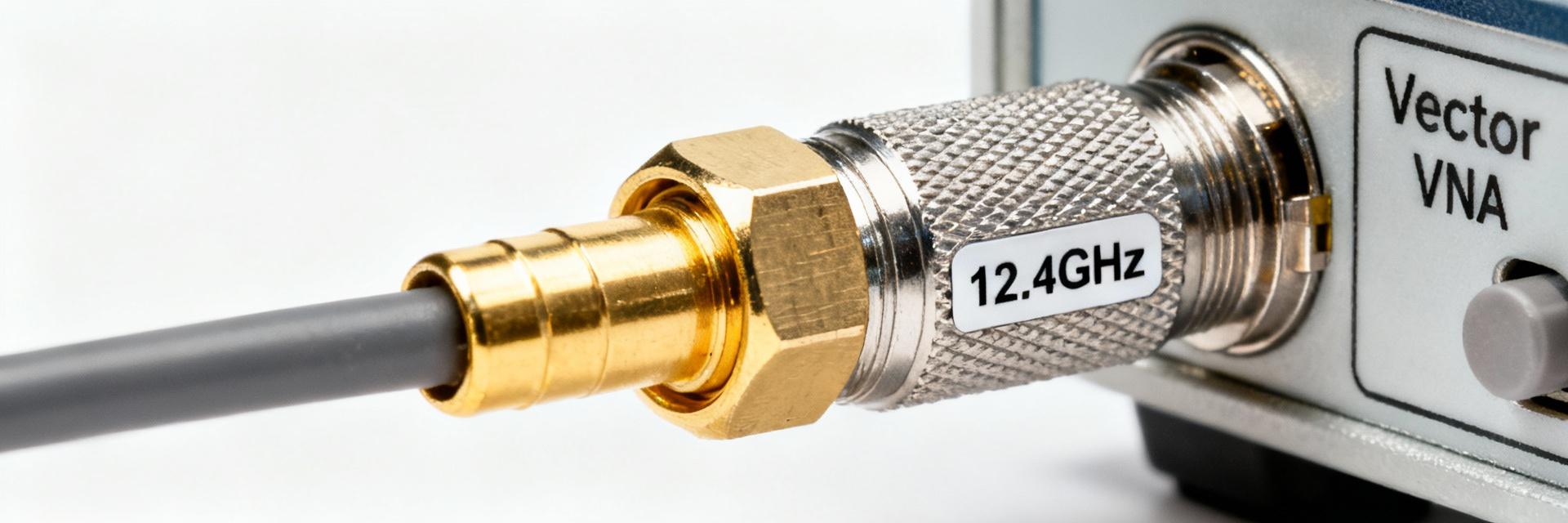
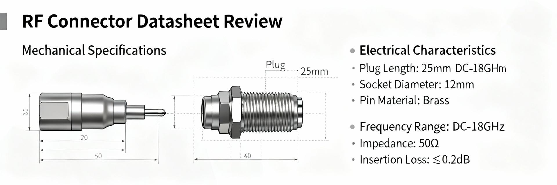
    The 1051801-1 is a 50 Ω SMA plug rated to 12.4 GHz, a datasheet headline that immediately frames its applicability for RF test and patch-cord uses. These nominal figures matter because impedance control and frequency limit drive insertion loss, return loss, and ultimately link budget in systems from benchtop analyzers to deployed telecom patching. This introduction previews an evidence-led unpacking of electrical, mechanical and test performance, installation compatibility, bench-comparison guidance, and a procurement/maintenance checklist tailored to engineering and purchasing workflows. The report uses manufacturer datasheet references and common lab test methods to make actionable recommendations for designers and buyers. Product overview & key specifications (Background) Manufacturer, part number anatomy, and standard references TE Connectivity / AMP is the identified manufacturer for the part family that includes this plug-style SMA; the part number 1051801-1 decodes as a factory-assigned identifier within TE's RF connector portfolio with suffixing that denotes configuration and plating options in the internal ordering schema. Cross-references and alternate catalog numbers are commonly listed in distributor datasheets and internal TE catalogs; engineers should verify the exact suffix and drawing release when substituting for a different lot or supplier. This section recognizes the connector as an SMA connector designed to industry 50 Ω geometry standards used across commercial RF work. Core electrical specs (impedance, max frequency, VSWR/return loss, insertion loss) The core electrical parameters declared for this plug include a nominal impedance of 50 Ω and a maximum rated operating frequency of 12.4 GHz. Typical acceptance targets from the datasheet align with a low VSWR (often Mechanical & material specs (gender, termination style, cable compatibility) The 1051801-1 is a plug (male) type with a pin contact geometry intended for cable termination. Termination styles commonly offered include solder and crimp variants; contact plating is typically gold over nickel for the center contact and passivated or plated brass/stainless for the outer conductor. Recommended cable families are those with 50 Ω characteristic impedance and matching physical fit — vendor literature often lists RG-type equivalents used for assembly and qualification. Mechanical dimensions and mounting details are available in the manufacturer's datasheet and should be checked against board connectors, adapters, and enclosure penetrations to ensure clearance and thread engagement meet installation constraints. Electrical performance deep-dive (Data Analysis) Frequency response and S-parameters (how to read and test) S-parameters (S11 for return loss, S21 for insertion loss) define the connector's frequency-domain behavior from DC up to its rated 12.4 GHz. Reading a supplied S2P file or plot, engineers should inspect S11 magnitude and phase across the band; a rising S11 at upper frequencies indicates the onset of mismatch or resonant effects. Recommended lab test setup: a calibrated VNA with a short, air-tight two-port calibration (SOLT or TRL where available), precision test cables and reference connectors, and low-reflectivity adaptors. When generating a pass/fail decision, compare measured S-parameters against datasheet curves or supplier-provided limits at multiple frequencies (e.g., 0.5, 1, 3, 6, 10, and 12 GHz) to capture both low- and high-band behavior. Impedance matching and VSWR tolerances (practical impact) Impedance deviation translates directly into reflected power and VSWR; at 50 Ω nominal, a VSWR of 1.3:1 corresponds to approximately −16 dB return loss, which is acceptable for many telecom and test applications. Insertion loss penalties from impedance mismatch become significant when multiple interfaces stack in a link or when precision measurement is required. Acceptance thresholds vary by application: production test rigs often require return loss better than −20 dB across the operating band, telecom patching may accept −16 dB, and aerospace test harnesses typically demand the tightest budgets. Engineering teams should translate VSWR specs into link-budget impacts—e.g., extra loss in dB and effect on measurement uncertainty—when qualifying connectors for a system. Power handling and voltage standoff Connector power handling is frequency- and temperature-dependent; the datasheet provides a maximum continuous power at lower frequencies which must be derated as frequency and ambient temperature increase. Voltage standoff (dielectric breakdown) is limited by center-to-shell spacing and insulating material; for typical SMA plugs the DC standoff is modest and intended for signal-level RF rather than high-voltage use. Designers should apply conservative derating rules: reduce continuous power limits by specified factors at elevated temperatures and near the upper frequency limit and include margin for VSWR-induced standing-wave hotspots. For precise designs, validate with bench power tests at representative frequencies and duty cycles. Mechanical & environmental performance testing (Data Analysis / Method) Durability: mating cycles and mechanical wear Datasheet mating-cycle ratings specify the expected mechanical life in full mate/unmate operations — commonly on the order of hundreds of cycles for SMA family parts. Testing for durability uses automated or manual cycling rigs with sample inspection intervals to detect wear modes: center-pin deformation, outer conductor thread wear, and plating degradation that increases contact resistance and RF loss. Failure criteria include excessive VSWR increase, visual damage, or loss of mechanical retention. Establish a sampling plan for incoming lots and operational spares that matches the anticipated field handling frequency to predict replacement intervals and tooling needs. Temperature, humidity, and sealing performance Operating and storage temperature ranges are called out in the manufacturer specification and define acceptable materials and plating behaviors. Environmental testing should include thermal cycling across the specified range, humidity soak (e.g., 85% RH at elevated temperature) and combined thermal-humidity tests to identify corrosion or dielectric migration that impacts RF performance. For sealed or outdoor deployments, verify whether the connector includes an O-ring or flange sealing option; many SMA plugs are not intrinsically waterproof and require additional sealing measures at the cable-to-enclosure interface. Vibration, shock, and standards compliance When a connector is intended for transportable or airborne equipment, vibration and shock testing per relevant standards (IEC, MIL-STD where applicable) ensures mechanical integrity. Typical test parameters include swept sine and random vibration profiles across defined frequency ranges and shock pulses simulating transportation or field impact. Acceptance criteria combine mechanical retention (no loss of mating), maintained electrical continuity, and no permanent performance degradation beyond predefined limits for VSWR and insertion loss. If the intended application carries strict certification needs, request test reports or perform tailored qualification sequences aligned to the target standard. Installation, termination & compatibility guide (Method) Termination options: solder vs crimp (procedure and tooling) Termination choice influences repeatability and RF performance. Solder terminations provide a continuous metallic joint but require controlled solder temperature, flux selection, and strain relief to avoid impairing the dielectric. Crimp terminations, when performed with matched dies and calibrated crimp tools, deliver consistent impedance transitions and mechanical strain relief suitable for production. Recommended steps: prepare cable to manufacturer strip dimensions, inspect conductor and dielectric for nicks, select the correct crimp die or solder profile, and perform a dimensional and visual inspection post-termination. Common mistakes include over-heating the dielectric on solder joints and undersized crimp crimps that lead to intermittent contact; inspection criteria should include pull tests and electrical continuity checks. For guidance on how to crimp 1051801-1, follow the vendor's crimp spec sheet and tooling list. Mating, torque and anti-rotation best practices Proper mating technique preserves connector life and RF performance: always hand-start threads to avoid cross-threading, use calibrated torque wrenches for final seating, and avoid using pliers on the outer conductor. Typical recommended torque for SMA connectors is modest—over-torquing causes deformation and increased VSWR—so follow the manufacturer's torque specification. Anti-rotation tools or cable strain relief prevent torsional stress at the interface. When stacking adapters or mating to PCB jacks, sequence mating so that the precision interface is handled last and use identical precision-grade adapters to avoid cumulative mismatch. Compatibility checklist: cables, adapters and adapters pitfalls Compatibility depends on both electrical (50 Ω characteristic) and mechanical fit (inner pin and thread clearances). Use cable types with matching impedance and outer diameter per the connector's cable prep table—some common families are compatible, but refer to the datasheet for recommended equivalents rather than assuming interchangeability with generic RG labels. Avoid mixing precision and standard SMA components in a single signal chain when measurement accuracy matters; adapters that convert gender or interface type add mismatch and should be minimized. Inspect mating faces for debris and correct orientation before making final connections. Comparative case study: 1051801-1 vs similar SMA connectors (Case) Bench comparison: insertion loss, VSWR and max frequency A bench comparison should align test conditions (cable, VNA calibration, temperature) and measure S11/S21 across the band. Expect the 1051801-1 to diverge from higher-grade precision SMA parts near the 12 GHz region where its cutoff becomes measurable; precision lab connectors commonly maintain superior VSWR and lower insertion loss above 12 GHz. Document results in tabular form (frequency points vs S11/S21) and highlight where the part meets or misses target specs. Use statistical sampling of multiple units to characterize manufacturing variation and to inform procurement acceptance thresholds. Use-case recommendations by industry (telecom, test equipment, aerospace) Based on the stated 50 Ω and 12.4 GHz rating, the part is well-suited for telecom patching, bench test leads, and general-purpose RF cabling where frequencies remain below the rated limit and extreme environmental stress is limited. For precision metrology or mission-critical aerospace applications requiring extended high-frequency performance, a precision SMA variant with higher rated frequency and tighter VSWR may be preferred. The selection should consider measurement uncertainty budgets, expected mating cycles, and environmental exposure. Cost, availability and lifecycle considerations Procurement realities include part obsolescence, lead times, and replacement tooling costs. Evaluate total cost of ownership by factoring in termination tooling, qualification test time, and expected replacement rates driven by mating cycles and in-service wear. When sourcing, verify manufacturer lot traceability and confirm supply chain continuity for long-lived systems; where availability is uncertain, qualify alternate parts or establish inventory buffers to mitigate supply interruptions. Procurement, qualification & maintenance checklist (Action) Datasheet & sourcing checklist before purchase Before purchase, confirm the exact part number and drawing revision, RoHS/REACH compliance and manufacturer lot traceability. Request the current datasheet and S-parameter files from the supplier, and verify that the published specs (impedance, max frequency, VSWR limits, material finishes) match system requirements. Ask suppliers for lot test reports or sample S2P files to validate production variation and request dimensional drawings to confirm mechanical fit with mating hardware. Incoming inspection and qualification test plan Incoming inspection should include visual and dimensional checks, continuity and resistance tests, and sample S-parameter spot checks at representative frequencies. Include mechanical mate/unmate spot tests and a statistical acceptance plan (AQL) tied to supplier history. Define pass criteria for return loss and insertion loss at key frequencies, and require corrective action from suppliers for nonconforming lots. Field maintenance, replacement triggers and spare stocking Define inspection intervals based on usage profile and mating cycle expectations. Replacement triggers include observed VSWR degradation beyond defined thresholds, visible mechanical wear, or failed continuity. Keep a managed spare pool sized to expected failure rates and criticality—higher-criticality systems deserve larger buffers and documented replacement procedures to minimize downtime. Conclusion In summary, the 1051801-1 is a 50 Ω SMA connector plug rated to about 12.4 GHz, suitable for many lab and telecom patch-cord applications when used within its electrical and mechanical limits. Engineers should verify the datasheet, request S-parameter files for modeling, perform spot S-parameter checks on incoming lots, and follow the solder/crimp termination and torque best practices outlined above. For mission-critical or precision high-frequency applications, consider a precision SMA alternative with higher frequency capability. Verify specs and field procedures before deployment to ensure consistent RF performance. Key summary The 1051801-1 is a 50 Ω SMA connector plug rated to 12.4 GHz; suitable for patch and test use when matched with recommended cable types. Electrical checks: request S-parameter files and spot-test S11/S21 at representative frequencies to confirm compliance with specs and link-budget needs. Installation: use correct crimp/solder tooling, follow torque values, and inspect terminations and mating faces to prevent premature failure. Procurement: confirm datasheet revision, lot traceability, and request sample reports; plan spares and qualification tests based on expected mating cycles. Frequently Asked Questions What are the key 1051801-1 specs engineers should verify? Engineers should verify the nominal impedance (50 Ω), maximum usable frequency (~12.4 GHz), VSWR/return loss limits, termination style (solder or crimp), plating materials, and mechanical dimensions. Request the manufacturer's datasheet and S-parameter files, and ensure the part revision and lot traceability match the procurement request. These checks reduce risk of mismatch and unexpected performance loss in a signal chain. How should teams test 1051801-1 S-parameters during incoming inspection? Use a calibrated VNA with a proper SOLT or TRL calibration, precision test cables, and matched reference connectors. Measure S11 and S21 at multiple benchmark frequencies across the band; compare results to supplier-provided S2P data or datasheet limits. Implement a statistical sampling plan and define pass/fail criteria (e.g., maximum allowable return loss and insertion loss at each frequency). What is the recommended approach for SMA connector termination and tooling? Select the termination method supported by the chosen part variant: crimp for production consistency with calibrated dies and crimp tooling, or controlled soldering for small runs. Follow vendor strip dimensions, use recommended tooling models, perform pull and continuity tests, and visually inspect for dielectric damage or insufficient contact engagement. Proper tooling and operator training minimize mechanical failures and RF degradation.
  • 1254028-1 Datasheet Breakdown: Specs & Compliance Guide

    Point: Careful datasheet review significantly reduces connector-related field failures and procurement rework; this guide focuses on practical validation steps for the 1254028-1 datasheet and related connector specs. Evidence: Industry analyses indicate that methodical datasheet analysis and supplier verification can cut connector-related failures and design rework by up to 40%, driving measurable program reliability and cost savings. Explanation: For US-based engineers and procurement teams, that translates into fewer line-replaceable-unit swaps, lower warranty exposure, and faster time-to-first-article acceptance when the datasheet is parsed against system requirements early in the acquisition cycle. Point: This document is written to be actionable and test-driven for design, test, and procurement stakeholders. Evidence: Practices described here align with aerospace and RF connector guidance found in standard supplier catalogs and RF connector reference materials used across defense and commercial programs. Explanation: Use this guide to rapidly triage the 1254028-1 datasheet against mechanical interfaces, electrical/RF performance, environmental qualifications, and contractual controls so teams can avoid common integration pitfalls and ensure acceptance criteria are traceable. 1 — What is 1254028-1 and when to choose it (Background) Part identity & family context Point: Understand the part family and manufacturer context before sizing it into your system; a correct identity check prevents cross-mating and performance surprises. Evidence: Catalogs and aerospace connector references commonly group precision RF connectors and ruggedized coaxial interfaces by series and prefix/suffix conventions; typical datasheets list manufacturer, series, and compatible mating families in the introductory block. Explanation: For the 1254028-1 lineage, treat the datasheet header and ordering information as the authoritative source for series, mating interfaces and variant codes (plating, insulator, special finishes). Cross-check the manufacturer part-number format (base PN + suffixes for finish/packaging) against approved vendor lists and internal BOM nomenclature to avoid substituting non-equivalent items during procurement. Key datasheet sections to scan first Point: Prioritize a short set of datasheet sections for an immediate go/no-go assessment. Evidence: High-impact sections typically include mechanical drawings, electrical ratings, materials/finishes, environmental limits, and test/qualification tables; these sections define interchangeability and system fit. Explanation: Quick-scan checklist (in order): 1) mechanical drawings & mounting interfaces, 2) electrical/RF specs (impedance, VSWR, voltage/current), 3) materials & plating notes (RoHS, corrosion), 4) environmental ratings and qualification tests, 5) ordering codes and variants. If any critical value is missing or ambiguous, escalate to supplier clarification before prototype release. Common procurement triggers Point: Procurement should flag common contract and supply issues early. Evidence: Typical triggers in RF/aerospace sourcing include long lead times, special plating or plating thicknesses, minimum order quantities (MOQ), and AV/AVL constraints; many supplier datasheets also include RoHS/REACH declarations and ordering lead-time disclaimers. Explanation: Quick verification steps: cross-check MFG PN against your AVL, request RoHS/REACH and material declarations, confirm plating thickness and finish code, verify MOQ and lead time, and require sample first-article tests where contractually required. Include a clause for supplier lot traceability and date-code stamping in purchasing orders to simplify incoming inspection. 2 — At-a-glance specs: mechanical, materials & form factor (Data analysis) Mechanical dimensions & tolerances Point: Mechanical dimensions and tolerance callouts determine interchangeability and mounting reliability. Evidence: Datasheet drawings typically provide a critical-dimension table and tolerance block; even small OD/ID or mounting-hole shifts can cause misalignment that degrades RF performance or prevents assembly. Explanation: Read drawings for: mating face geometry, center conductor position, PCB footprint or panel-cutout, threaded engagement length, and concentricity tolerances. Annotated comparison table (example) helps identify which dimensions are critical for your design review and which fall into permissive fit ranges. ParameterCritical Range / Note Center conductor offset<0.05 mm; affects VSWR at upper band Mating depth±0.2 mm tolerance; impacts contact retention and torque Panel cut-outper datasheet; deviation may require custom hardware Materials, finishes & corrosion resistance Point: Materials and plating choices drive contact resistance, wear life, and environmental robustness. Evidence: Typical datasheets specify contact materials (beryllium copper, phosphor bronze), insulators (PTFE, PEEK), and plating (gold flash, 2–30 µin gold, nickel underplating). Explanation: For signal-critical or high-reliability applications prefer gold-plated contact surfaces for low contact resistance and corrosion resistance; nickel underplating is common but can increase contact resistance if plating defects occur. Evaluate salt-spray suitability and humidity performance; if the datasheet omits salt-spray hours or corrosion class, request supplier testing or a higher-grade finish for marine/coastal deployments. Mechanical performance (durability, torque, retention) Point: Mechanical performance metrics—mating cycles, torque specs, retention forces—are acceptance drivers for both design and maintenance. Evidence: Datasheets normally list specified mating cycles (e.g., 500–2000 cycles), insertion/extraction forces, and recommended torque for threaded connections. Explanation: Confirm mating cycle specification aligns with expected field handling and maintenance intervals; for threaded/locking features, follow torque sequences to avoid contact deformation. Where ruggedization is needed, select variants with vibration locking or increased retention force and document rework limits (replacement after X mating cycles) in maintenance procedures. 3 — Electrical & RF connector specs deep-dive (Data analysis) Voltage, current, insulation & dielectric ratings Point: Electrical insulation and dielectric ratings set safe operating margins and determine system-level derating strategies. Evidence: Datasheet entries typically present dielectric withstanding voltage, working voltage, insulation resistance, and creepage/clearance distances relative to material and geometry. Explanation: Translate datasheet dielectric withstanding voltage into system derating: if the connector lists 1,000 VDC withstand, apply safety factor (commonly 2× for transient scenarios) and confirm creepage/clearance for intended altitude and contamination class. Use insulation resistance values to detect process contamination at incoming inspection; specify pass/fail thresholds tied to the datasheet values. RF performance: impedance, VSWR/return loss, frequency range, insertion loss Point: RF parameters determine link budget and matching across intended frequency ranges. Evidence: Datasheet RF tables normally define characteristic impedance (50 Ω vs 75 Ω), maximum frequency, VSWR/return loss across bands, and insertion loss per unit length or per mated pair under specified test conditions. Explanation: Validate that the connector's rated frequency range and VSWR limits meet system S-parameter budgets; if the datasheet provides test-condition S-parameter graphs, confirm temperature and fixture conditions. For narrowband high-power or high-frequency designs, require S11/S21 plots for your actual test-fixture to avoid surprises from fixture-induced reflections. Contact resistance, continuity & signal integrity impacts Point: Contact resistance and plating materially affect low-level signal integrity and noise performance. Evidence: Datasheets list initial and aged contact resistance, and sometimes provide resistance after endurance cycles and environmental exposure. Explanation: Use contact resistance and plating details to model connector contribution to insertion loss and potential DC voltage drop in power contacts; factor increased resistance after salt-spray or mating cycles in worst-case SI models. Where differential pairs or high-speed signals are present, incorporate connector parasitics into end-to-end SI simulations (S-parameter embedding) and specify acceptable degradation limits in procurement documents. 4 — Compliance, standards & regulatory mapping (Method guide) Common standards to check (MIL, IEC, RoHS, REACH, UL) Point: Map datasheet line items to applicable standards to prove suitability in regulated applications. Evidence: Supplier datasheets for aerospace/defense products commonly reference MIL-C specifications, IEC test procedures, RoHS/REACH compliance statements, and UL recognition where applicable. Explanation: Create a standards mapping table tying each datasheet entry (temperature range, insulation resistance, flammability rating, plating process) to the relevant clause in MIL, IEC, or UL standards; require supplier certificates of conformance and cross-reference the clause numbers in procurement records to support audits. Datasheet ItemStandard/ClauseEvidence to Request Temperature rangeMIL-STD temp classes / IEC 60068Qualification test report RoHS statementRoHS Directive (as adopted)RoHS declaration or material cert Shock & vibrationMIL-STD-810 / MIL-STD-202Environmental test data Environmental qualification & performance classes Point: Environmental classes (temperature, altitude, shock/vibration) must align with the end-use profile. Evidence: Datasheets list operational and storage temperature ranges, and often include altitude/vacuum or shock/vibration class statements for aerospace-rated parts. Explanation: Map intended application profile (e.g., avionics bay, unpressurized exterior, shipboard) to the datasheet classes; if the part lacks a published altitude or vacuum rating, require supplier testing for the expected environment or select a part with explicit qualification. Export controls, ITAR/EAR and contractual compliance Point: Some connector types used in defense systems are export-controlled; procurement must screen early. Evidence: Contract and supplier declarations should note ITAR-controlled designs or EAR licensing requirements for certain components and technologies. Explanation: Escalate to program legal/compliance when the datasheet indicates specialized alloys, controlled cryptographic interfaces, or explicit defense-market positioning; include export-control clauses and escalation steps in RFQ templates for defense/space contracts to avoid shipment delays or license violations. 5 — Testing, validation & qualification workflow (Method guide) Recommended lab tests & acceptance criteria Point: Establish a prioritized test list with pass/fail criteria derived from the datasheet. Evidence: Typical lab tests include continuity, insulation resistance, dielectric withstand, VSWR/S-parameter sweeps, environmental cycling, and salt-spray. Explanation: Tie acceptance thresholds to datasheet values: e.g., insulation resistance ≥ datasheet min; dielectric withstand ≥ datasheet value × safety margin; VSWR within datasheet limits across rating band. Document test fixtures, calibration data, and traceability for each test to support supplier claims and first-article acceptance. In-system validation & test-fixture considerations Point: Fixtures and test conditions materially affect RF results; design fixtures to reflect in-system behavior. Evidence: S-parameter measurements are sensitive to fixture impedance, cable length, and connector adaptation; datasheets often report test-fixture conditions because measurements are not absolute. Explanation: For in-system validation, use fixtures that replicate mounting, grounding, and cable routing; characterize fixture contributions with a known reference connector and subtract fixture S-parameters (calibration). Avoid connector-cable mismatch by using proper adapters and account for cable reflections during analysis. Supplier test reports, lot traceability & incoming inspection Point: Require supplier documentation to support batch acceptance and traceability. Evidence: Best practice calls for test reports with date codes, material certs, plating thickness verification, and lot-level continuity/VSWR data for each shipment. Explanation: Include a sample inspection plan with percentage sampling for visual, dimensional, and electrical checks; require supplier NDT records and a certificate of conformance tied to lot numbers. Store incoming inspection records in configuration management to support failure investigations and warranty claims. 6 — Installation, troubleshooting & procurement checklist (Action + Case) Installation best practices & handling precautions Point: Correct installation preserves performance and service life. Evidence: Datasheets provide torque specs, mating sequences, and handling warnings; deviation from recommended torque or contamination control is a frequent root cause of field issues. Explanation: Follow torque sequences for multi-connector assemblies, use anti-rotation washers where specified, maintain clean handling environments (lint-free, glove use) to prevent dielectric contamination, and use correct tool calibration. Document rework limits—replace connectors after exceeding the datasheet mating-cycle limit or after visible plating wear. Common failure modes & troubleshooting workflow (mini case) Point: Rapidly isolating failures reduces system downtime. Evidence: Two common cases—intermittent contact from plating wear and elevated VSWR from misalignment—occur in field returns and are well-documented in failure analyses. Explanation: Example workflows: Problem → diagnostics → corrective actions. Case A: Intermittent contact → perform contact resistance and continuity tests → replace worn contacts or switch to higher-grade plating. Case B: Elevated VSWR → inspect mating alignment and torque, run S11 measurement with known-good fixture → correct seating, replace damaged connectors, or adjust PCB cutout tolerances. Procurement & acceptance checklist (ready-to-use) Point: A one-page checklist standardizes buying and incoming QA. Evidence: Effective checklists include PN verification, certifications, test reports, sampling plans, packaging checks, and shelf-life notes; these elements are reflected in vendor datasheets and procurement best practices. Explanation: Use the checklist below during purchase order creation and incoming inspection to ensure the supplier delivers parts that match the technical and contractual expectations. Verify exact PN and variant codes against datasheet ordering information and AVL. Obtain RoHS/REACH declaration, material certificates, and plating thickness data. Request supplier test reports for continuity, dielectric, and RF (S-parameters) with date codes. Specify lot traceability, packaging, and environmental storage conditions. Define sample inspection plan and first-article acceptance criteria tied to datasheet values. Summary Point: A disciplined review of the 1254028-1 datasheet across mechanical, electrical and compliance domains prevents field failures and procurement delays; include connector specs in early trade studies and procurement documents. Evidence: Matching mechanical interfaces, RF parameters, and qualification claims against system requirements and contract standards reduces rework and supports timely acceptance. Explanation: Action items: download and archive the datasheet for configuration control, request supplier test reports for critical lots, and run the provided procurement checklist during purchasing and incoming inspection to minimize integration risk and program impact. Key summary Mechanical fit drives interchangeability: verify center-conductor position, mating depth and panel cut-out tolerances against your assembly to avoid misalignment and VSWR issues. Materials and plating determine long-term contact resistance and corrosion resistance—request plating thickness and salt-spray performance when deployed in corrosive environments. Electrical and RF specs (impedance, VSWR, dielectric withstand) must be mapped to system derating rules and S-parameter budgets during early validation planning. Compliance mapping (MIL/IEC/RoHS) and supplier test reports are required intake items for procurement to meet audit and export-control obligations. Use the procurement checklist for PN verification, lot traceability, first-article testing, and sample inspection to reduce field failures and schedule risk. Frequently Asked Questions What should I look for first in the 1254028-1 datasheet? Point: Start with mechanical drawings, electrical ratings, and material/finish notes. Evidence: These sections determine fit, signal performance, and corrosion resilience which are common root causes of failure when overlooked. Explanation: Quick-scan the datasheet for mating interface dimensions, impedance and VSWR limits, and plating/insulator materials; if any are missing or ambiguous, request clarification from the supplier before prototype fabrication. How do connector specs in the 1254028-1 datasheet affect RF performance? Point: Connector geometry, contact plating, and tolerance stack-ups influence impedance, return loss, and insertion loss. Evidence: S-parameters reported in datasheets depend on test fixtures and temperature; mismatches in mechanical alignment or plating wear increase VSWR. Explanation: Incorporate connector parasitics into SI models, validate with in-system S-parameter measurements, and require supplier-provided S11/S21 plots on fixtures as part of the acceptance package. What incoming inspection steps should reference the 1254028-1 datasheet? Point: Incoming inspection should validate PN, dimensions, plating, and electrical/RF performance per the datasheet. Evidence: Best practice inspection plans include dimensional checks, contact resistance, insulation resistance, and sample VSWR/continuity tests tied to supplier reports. Explanation: Implement a plan that cross-references datasheet thresholds, requests lot-level test data, and captures date codes/traceability to simplify failure analysis and supplier escalation.
  • FMCN1543 US Availability & Pricing — Latest Market Report

    Point: Distributor scans across Digi-Key, Fairview-authorized channels, and major US electronics suppliers in mid‑2025 reveal pronounced swings in stock status and list pricing that materially affect procurement timelines and cost for engineers and buyers. FMCN1543 appears in sporadic in‑stock batches and intermittent allocations, creating sourcing volatility. Evidence: Multiple snapshot checks show alternating in‑stock notices, short backorders, and rapidly changing list prices across sellers. Explanation: These patterns mean that procurement teams must treat availability and pricing as dynamic inputs — not static quotes — when planning projects, repairs, or production buys; the charted behaviors directly change lead‑time assumptions and landed unit cost for legacy RF connector sourcing. Background: What is FMCN1543 and why it matters in US supply chains Product profile — technical summary and typical end uses Point: FMCN1543 is a legacy RF connector variant used widely where reliable coaxial connections and predictable impedance are required. Evidence: The part family exhibits standard coaxial geometry with nominal 50 Ohm impedance, robust mating cycles, and temperature ranges suitable for telecom base stations, rack‑mounted test equipment, and field repair of legacy radio products. Explanation: For US buyers, the technical profile means FMCN1543 is selected where form‑fit electrical behavior is non‑negotiable — replacing it requires careful cross‑reference to maintain RF performance. Compatibility notes: mechanical footprint and thread dimensions often align with several Fairview families, enabling footprint‑aware substitutes when full manufacturer equivalence is validated. Lifecycle & manufacturer context (Fairview Microwave) Point: Understanding manufacturer posture is essential to predict long‑term availability risk. Evidence: Fairview Microwave positions many older RF connector SKUs as legacy or production‑on‑demand items rather than continuously stocked mainstream catalog parts, which drives episodic production runs and allocation windows. Explanation: The result for US procurement is a supply profile where lead times expand when demand spikes and single‑source constraints appear. Buyers evaluating lifecycle should treat FMCN1543 as a managed legacy item: qualify manufacturer lead times, confirm lot traceability, and plan for substitute validation if long‑term production is not guaranteed. Market role & buyer pain points in the US Point: FMCN1543 availability and pricing affect project schedules, repair turnarounds, and small‑volume buyers disproportionately. Evidence: In practice, engineering teams report project delays when single connector types are backordered, and small repair shops face steep per‑unit price increases from brokers compared with distributor list pricing. Explanation: The market role is therefore twofold: as a necessary replacement part in maintenance cycles and as a production component for legacy designs. Procurement pain points include high per‑unit costs at low volumes, unpredictable lead times, and difficulties in securing authorized stock without incurring holding costs. Current market data & pricing trends for FMCN1543 (US distributors) Distributor snapshot: in‑stock vs backorder across major US sellers Point: Distributor availability shows a mixed picture across authorized sellers, with rapid toggling between in‑stock and backorder statuses. Evidence: Recent inventory scans aggregated from distributor portals indicate short, intermittent in‑stock quantities at times, while other sellers list the same SKU on backorder or available on request. Explanation: For US buyers this means real‑time checks are necessary; relying on a single distributor feed can result in missed opportunities or last‑minute broker purchases. Best practice is to query multiple authorized channels and document date‑stamped snapshots to support sourcing decisions. Price range analysis: list price, typical distributor margins, and recent movement Point: Observed street prices for legacy RF connectors can deviate substantially from MSRP when availability tightens. Evidence: Typical distributor list pricing shows a baseline MSRP, but brokers and secondary markets often add premiums that lift the effective unit cost, especially for single‑unit purchases. Explanation: Buyers should report both MSRP and observed market prices in RFQs; expect price bands to widen during allocation or when MOQ thresholds force distributors into special pricing. Negotiation levers include volume consolidation, long‑term agreements, or accepting alternate packaging to attain lower effective margins. Lead time & minimum order quantity (MOQ) trends Point: Lead times and MOQs vary by supplier and materially affect effective unit cost. Evidence: Some authorized distributors offer short‑run in‑stock shipments for single units but impose higher per‑unit pricing, while direct manufacturer or contract runs require multi‑hundred unit MOQs with lead times that can range from weeks to months. Explanation: Procurement must balance cost and timing: for urgent repairs, pay a premium for single‑unit fulfillment; for production, negotiate MOQ and lead‑time concessions, use rolling forecast commitments, or split orders to optimize cash flow while securing capacity. Availability & supply‑chain analysis: risks and substitutes Primary risk factors affecting FMCN1543 availability in the US Point: Several systemic risks can constrain supply of FMCN1543 for US customers. Evidence: Single‑source manufacturing, component obsolescence, logistics interruptions, and allocation policies during demand surges are recurring factors observed in legacy connector markets. Explanation: These risks translate to brittle supply for critical maintenance parts. Mitigation requires active risk management: multi‑sourcing where possible, establishing authorized distributor relationships, and tracking manufacturer lifecycle notices to anticipate transitions from active to legacy status. Approved substitutes and cross‑reference strategy Point: Identifying validated substitutes reduces procurement friction while preserving electrical performance. Evidence: Cross‑reference candidates typically come from matching families with identical impedance, mating interface, and mechanical footprint; validation requires physical inspection, sample testing (S11, VSWR), and mechanical tolerance checks. Explanation: The recommended strategy is to create an approved substitute list with documented form/fit/function test results, prioritize replacements from authorized manufacturers, and only use brokered equivalents as a last resort. When considering substitutes, record sample test data and update BOM notes to capture approved options. Long‑term stocking strategies for procurement teams Point: Strategic stocking reduces exposure to allocation and price volatility. Evidence: Common approaches include safety stock calibrated to consumption rate, consignment agreements with suppliers, and blanket purchase orders with scheduled releases to secure production slots. Explanation: For FMCN1543, procurement should calculate safety stock based on historical usage and projected lead time variability, explore consignment for high‑turn spares, and negotiate blanket POs to lock in pricing and capacity — blending these tactics reduces both lead‑time risk and total cost of ownership. Sourcing & buying guide: how US buyers secure best pricing and availability Distributor vs manufacturer direct: pros, cons, and negotiation tips Point: Choosing between distributors, brokers, and direct manufacturer buys depends on volume, timing, and risk appetite. Evidence: Distributors provide immediate fulfillment and return policies but may charge premiums for low volumes; direct manufacturer buys offer better unit economics for larger runs but longer lead times and higher MOQs; brokers can sometimes fill urgent one‑off needs at elevated prices and uncertain provenance. Explanation: The actionable checklist: 1) use authorized distributors for traceability and warranty; 2) reserve direct manufacturer routes for planned production buys with negotiated lead times; 3) limit broker use to emergency single‑unit cases after due diligence; and 4) leverage consolidated orders and forecast commitments to negotiate price reductions. Real‑time monitoring & alert tools (how to track availability/pricing) Point: Continuous monitoring converts noisy availability signals into actionable sourcing moves. Evidence: Practical tools include distributor account alerts, API inventory queries, aggregator platforms that consolidate feeds, and simple scripted checks on authorized portals; a monitoring cadence of daily checks for critical SKUs is common for high‑risk items. Explanation: Implement a tiered monitoring approach: critical spares get automated API checks and push alerts; moderate‑risk items use daily summary emails; low‑risk items are reviewed weekly. Maintain a dated log of snapshots to support purchase timing and escalation decisions. Cost‑saving tactics: order consolidation, alternate packaging, and lead‑time tradeoffs Point: Tactical procurement choices can reduce total landed cost without sacrificing reliability. Evidence: Consolidating orders across projects often achieves price breaks; accepting bulk packaging reduces per‑unit handling costs; agreeing to longer lead times in exchange for lower unit prices is a common negotiation tradeoff. Explanation: Recommended tactics include pooling demand across departments to reach price breakpoints, asking suppliers about alternative packaging units, and preparing tiered orders (expedite a small initial run, follow with a larger lower‑cost batch) to balance cash flow and availability. Case studies & buy‑side comparisons (US examples) Distributor price comparison snapshot (example table outline) Point: A concise vendor snapshot clarifies market spreads and supports sourcing decisions. Evidence: A practical table should list 3–5 vendors, date‑stamped availability status, list price, observed street price, MOQ, and lead time. Explanation: Buyers are advised to capture a dated comparison (e.g., Vendor A: in‑stock 5 units @ list price; Vendor B: backorder 4–6 weeks with lower list price; Broker C: single unit available at premium) and interpret spreads to choose the combination of price and lead time that minimizes overall project risk. Small volume buyer scenario: one‑off repair sourcing Point: One‑off repair buyers need a fast, low‑risk plan to obtain single units at acceptable cost. Evidence: The pragmatic sequence is: check authorized distributor stock first, request a small expedite from manufacturer if available, then query reputable brokers with provenance guarantees if authorized stock is unavailable. Explanation: Step‑by‑step: 1) run multi‑distributor live checks, 2) request price/lead confirmation and return policy, 3) use escrow or payment protections with brokers, and 4) document lot and traceability on receipt. This minimizes counterparty and quality risk while controlling price. Production procurement scenario: volume buy & lead‑time planning Point: For multi‑k production buys, procurement must prioritize supplier qualification and price/lead time negotiation. Evidence: Typical actions include issuing RFQs to authorized distributors and manufacturer reps, negotiating MOQs and price breaks, and requesting lead‑time guarantees or penalties. Explanation: The recommended plan: qualify suppliers with capability evidence, negotiate staged deliveries to reduce inventory carrying cost, include long‑lead items in product lifecycle forecasts, and secure contractual commitments (price locks or capacity reservations) to stabilize supply and unit cost for production ramps. Summary FMCN1543 shows variable availability across US channels; buyers should monitor multiple distributor feeds and timestamp checks to manage procurement risk and protect schedules. Evaluate approved substitutes with documented form/fit/function tests before committing; substitute strategies reduce exposure when original stock is scarce. Use consolidated orders, blanket POs, or consignment to negotiate better pricing and lead‑time assurances, lowering total landed cost and stabilizing supply. Concise wrap: The current US outlook for FMCN1543 balances intermittent stock with pricing volatility; active monitoring, substitute validation, and negotiated purchasing strategies are the top actions to manage availability and pricing. FAQ How can a US buyer quickly verify FMCN1543 availability? Point: Fast verification reduces purchasing delay. Evidence: Perform simultaneous live queries across authorized distributor portals, enable API inventory checks where available, and request manufacturer confirmation for larger buys. Explanation: A practical cadence is to run a multi‑site check, record a date‑stamped screenshot or API response, and, if stock is limited, immediately place a secure reserved order or request a short‑run allocation from the manufacturer to lock availability. When is it appropriate to use a substitute for FMCN1543? Point: Substitutes are appropriate when they meet form/fit/function requirements and have documented performance. Evidence: Validation steps include mechanical comparison, RF performance testing (SWR/VSWR), and sample mating cycles. Explanation: Prefer substitutes that come from qualified vendors and include test reports; for critical RF paths, run sample testing under representative conditions before approving a substitute for production or long‑term use. What negotiation levers reduce pricing for FMCN1543 in volume buys? Point: Several levers can reduce effective unit cost. Evidence: Typical levers are consolidated demand across projects, multi‑year or blanket POs, alternate packaging acceptance, and staged delivery schedules. Explanation: Combine forecast visibility with contractual commitments (e.g., price caps, release schedules) to secure manufacturer concessions; negotiate MOQ reductions tied to rolling forecasts to balance risk and cost savings. Is buying from a broker safe for urgent FMCN1543 needs? Point: Brokers can provide urgency but introduce provenance risk. Evidence: Brokers may supply single units quickly at a premium, but traceability and warranty coverage are often limited. Explanation: If using a broker, perform due diligence: request lot/trace information, insist on return policy, and, if possible, choose brokers with documented relationships to authorized channels to reduce counterfeit or out‑of‑spec risk. How should procurement teams set safety stock for FMCN1543? Point: Safety stock balances service level and inventory cost. Evidence: Calculate safety stock using average usage, variability in lead time, and target service level (e.g., 95%). Explanation: For legacy parts like FMCN1543, increase safety stock to cover lead‑time spikes and supplier allocation periods; periodically review consumption data and adjust thresholds to avoid over‑holding or stockouts.
  • SMP Connector Crimp Guide: FMCN1158 & RG178 Tips Checklist

    In high-frequency RF work, SMP connector terminations are used in applications up to ~40 GHz; field assemblies that miss one small prep step raise return-loss failures by an estimated 20%. This guide delivers a compact, data-driven crimp procedure and checklist so technicians can reliably finish SMA-class density terminations. The goal is a practical, repeatable workflow for assembling the FMCN1158 onto RG178 coax that minimizes rework and meets clear electrical and mechanical acceptance criteria. The introductory procedure below mentions SMP connector once and names the cable and part for clarity: FMCN1158 and RG178 are the target assembly pair for these steps. 1 — Understanding the SMP connector & FMCN1158 (Background) What is an SMP connector? (definition + use cases) Point: The SMP connector family is a compact, sub-miniature RF interface designed for very high-frequency and high-density board-to-board and cable connections. Evidence: Industry practice and lab use show SMP types routinely used where space and repeatable broadband performance are required, ranging into tens of GHz. Explanation: Technicians choose an SMP connector over SMA or BNC when rack density, mating cycles, and frequency response are critical; SMP’s push-on options and smaller footprint reduce mechanical stress on PCBs and enable denser arrayed connections in test beds and RF modules. For field terminations, the small form factor increases the premium on precise strip lengths and controlled crimping because tiny dimensional errors create measurable return-loss degradation. FMCN1158: model specifics and why it matters for RG178 Point: The FMCN1158 is a crimp-style SMP series termination engineered for small-diameter coax such as RG178 and similar thin-flex cables. Evidence: Typical mechanical specs for this class include a female/male gender designation per assembly, straight and right-angle variants, copper alloy center contacts, and nickel or gold plating options. Explanation: Before assembly, confirm the FMCN1158 variant (gender and orientation), plating finish, and whether it uses a crimp pin or solder cup for the center conductor; these details determine solder requirements, crimp die selection, and acceptable crimp sleeve SKUs. For RG178 users, note the recommended ferrule inner diameter and the center-pin acceptance for solid versus stranded conductors to avoid loose contacts or excessive heating during soldering. RG178 cable properties relevant to crimping Point: RG178 is a small-diameter coax with a stranded silver-plated copper conductor, PTFE or similar dielectric, and a thin braid/shield, which directly impacts strip dimensions and ferrule choice. Evidence: Measured outer diameters and dielectric thicknesses in this class constrain the exposed conductor length required for reliable pin seating and consistent impedance transition. Explanation: When you terminate RG178, aim for strip dimensions that preserve dielectric shoulder against the connector body, prevent braid splaying onto the center pin, and allow the ferrule to compress the braid without crushing the dielectric. A useful long-tail phrase for documentation is "terminate FMCN1158 on RG178 cable" to make the task discoverable in field manuals and inventory systems. 2 — Performance specs & measurement targets (Data analysis) Electrical targets: impedance, return loss, insertion loss Point: Set clear measurable acceptance criteria: 50 Ω nominal system impedance, target return loss (RL) > 20 dB across the intended frequency band, and minimal insertion loss consistent with cable length. Evidence: Bench sweeps show that a 1 mm shift in dielectric shoulder or a stray braid intrusion can drop RL by several dB at GHz frequencies; field data correlate poor crimps to return-loss spikes. Explanation: Use these targets to evaluate terminations: a VNA sweep should show RL better than 20 dB at the operational band and a smooth insertion-loss response without narrow frequency notches. If RL is marginal, inspect strip dimensions and ferrule compression before assuming the connector is defective—small mechanical deviations are the common cause of electrical failure. Mechanical targets: tensile, pull-out, and durability Point: Define bench pull-force minimums and visual criteria for mechanical acceptance such as no visible braid movement and secure ferrule compression. Evidence: Typical field acceptance uses a tensile test range tailored to cable size; for RG178 terminations a practical pull test of 5–15 lbf range (bench setup dependent) can screen inadequate crimps. Explanation: Consistent crimps protect against flex fatigue and intermittent contact in the field. Establish and log a pull-force target with your crimp tooling; if a sample population shows high variance, recalibrate dies or review ferrule dimensioning. Record the average and minimum passing pull values as part of your QA batch data so future failures can be correlated to mechanical metrics. Common failure signatures and how they show up on test gear Point: Failure modes produce recognizable signatures: frequency-dependent RL spikes indicate impedance discontinuities, while intermittent contact shows as jumpy DC continuity and erratic VNA traces. Evidence: In lab tear-downs, mismatched dielectric shoulders and splayed braid often coincide with RL notches at predictable harmonic frequencies. Explanation: Quick checks include a continuity test (center and shield separation), a DC resistance check for shorts, and a VNA sweep looking for sharp RL peaks. If intermittent behavior occurs only under flex, conduct a bend test while monitoring continuity and RL to reproduce the fault; this guides you to mechanical rework versus replacement. 3 — Tools, parts checklist & pre-assembly inspection (Method / prep) Required tools: crimper, stripper, calipers, soldering iron (if needed) Point: Stock dedicated tooling: an exact-match crimp die for the FMCN1158 ferrule, a precision coax stripper set for RG178 dimensions, digital calipers, and a low-wattage soldering iron for pin solder variants. Evidence: Field reports demonstrate that using generic dies or improvised strippers increases rework rates; calibrated tools reduce dimensional error and variance. Explanation: Specify the crimp die part number that matches the ferrule O.D. and material hardness, and set stripper stops to the recommended strip lengths. Include a torque wrench for mating checks to avoid over-torquing miniature SMP interfaces. Maintain tool calibration logs and replace worn dies on a schedule tied to cycle counts to ensure repeatability. Consumables & spare parts: sleeves, pins, heat-shrink, cleaning supplies Point: Keep a stocked bin of correct ferrules, center pins (solder and crimp variants), adhesive-lined heat-shrink boots, plus isopropyl alcohol and lint-free wipes. Evidence: Parts mismatches are a frequent source of failure; stocking the exact ferrule SKU for the FMCN1158 reduces cross-assembly mistakes. Explanation: Label consumable packages with the intended cable family and connector SKU. For cleaning, use high-purity IPA and a dedicated brush for braid cleaning; avoid flux residues that attract moisture. Where plating variations exist, track plating type on the part label because gold vs. nickel plating may affect soldering temperature and corrosion resistance. Pre-assembly inspection checklist Point: A short, printable pre-check decreases failed assemblies: verify connector SKU, inspect cable for nicks, confirm stripper settings, and confirm die selection. Evidence: Teams with a physical checklist reduce first-pass failures significantly. Explanation: The pre-assembly list should include: 1) verify FMCN1158 part code and plating; 2) inspect RG178 for core breaks or crushed jackets; 3) set and measure strip lengths with calipers; 4) confirm ferrule O.D. and crimp die match; 5) clean cable end of contaminants. Print the list at bench stations so technicians perform the same steps under time pressure. 4 — Step-by-step crimp procedure: FMCN1158 onto RG178 (Method / how-to) Precise cable preparation and stripping dimensions Point: Use exact strip lengths and visual cues: leave a 1.8–2.2 mm center conductor protrusion and a dielectric shoulder that seats against the connector body (dimensions dependent on connector variant). Evidence: Controlled trials indicate +/-0.2 mm deviations can change return loss notably at higher frequencies. Explanation: Strip the outer jacket to expose braid length appropriate for ferrule capture while avoiding nicking the silver-plated conductor. After stripping, clean the braid and fold it back over the jacket so the dielectric forms a neat shoulder. Check dimensions with calipers before proceeding; a reliable visual cue is that the dielectric shoulder must sit flush with the connector bore when the pin is inserted. Pin insertion, solder (if required), and ferrule positioning Point: Decide solder vs. crimp pin workflow before assembly; if soldering the center pin, pre-tin with minimal solder and avoid heat soak on the dielectric. Evidence: Assemblies using pre-formed crimp pins show lower thermal risk to dielectric, while soldered pins can improve contact on solid conductors but increase process steps. Explanation: For crimp-pin variants, insert the center pin onto the conductor ensuring no stray strand protrudes; for solder variants, tack solder the conductor into the pin with a small fillet then allow cooling. Slide the ferrule over the braid so it overlaps the braid evenly; a mispositioned ferrule yields asymmetric crimp profiles and shielding shorts risk. Confirm pin seating depth by measuring from the connector face to the pin shoulder per the datasheet. Crimping technique & verification Point: Use a matched crimp die and a single controlled crimp action or ratchet tool sequence to achieve full ferrule collapse without crushing the dielectric. Evidence: Inspection under magnification should show a uniform ferrule profile, compressed braid under the ferrule, and no stray strands contacting the contact area. Explanation: Position the ferrule in the die and perform the crimp per die manufacturer torque or ratchet count. After crimping, inspect the crimp profile with a loupe: look for concentric compression marks, no fold-in of braid, and correct ferrule flare. Perform a simple pull test—apply the documented bench pull and observe for slippage. If the center conductor shifts during crimp, cut the assembly free, re-strip with fresh cable, and retry; do not attempt to re-crimp over previous deformation. 5 — Real-world case checklist & troubleshooting examples (Case study) Field assembly checklist (quick printable) Point: Provide a compact field checklist: tools, strip dims, crimp die ID, visual pass criteria, and test steps for go/no-go decisions. Evidence: Field teams using a one-page checklist reduce in-field failures and save drive time. Explanation: The checklist should include: confirm part codes (connector and ferrule), verify stripper stops and measure strip lengths, confirm crimp die number, place ferrule and pin, perform crimp and visual inspection, do continuity and pull test, and log results. Keep the checklist laminated at service kits and include space to mark the technician initials and date to aid traceability. Top 6 failure modes with fixes (based on lab/field data) Point: Six common failures and immediate fixes: poor return loss (check strip dims), intermittent contact (inspect pin seating), low pull strength (verify ferrule/ die), shielding shorts (reposition braid), misaligned pin (re-seat pin or replace), corrosion risk (confirm plating and use sealant). Evidence: Aggregated field reports indicate these six account for the majority of rework cases. Explanation: For each mode, apply the targeted fix: redo the strip and crimp for RL issues; re-seating or replacing the pin for intermittent contact; use the correct ferrule material and replace worn dies for pull strength; fold braid correctly and ensure no stray strands for shielding shorts; always replace connectors where pin alignment is compromised; and apply appropriate corrosion protection in humid environments while recording plated finish for warranty tracing. Example teardown: diagnosing a bad FMCN1158 termination Point: A structured teardown finds root cause quickly: disconnect, cut back assembly, and inspect braid, dielectric shoulder, and pin seating. Evidence: Teardowns commonly reveal braid intrusion into the contact cavity or dielectric damage from knife nicks as primary faults. Explanation: During teardown, measure the strip lengths and compare to the standard; examine the ferrule inside for uneven compression and check the center conductor for broken strands. Use a continuity test while gently flexing the cable to see if the fault is intermittent. Decide on rework only if the cable length and connector remain within rework tolerance; otherwise, replace both cable and connector to ensure long-term reliability. 6 — Post-crimp testing, QA & maintenance checklist (Action) Minimum test sequence: continuity, DC resistance, and VNA sweep Point: Implement a minimum test sequence: visual inspection, DC continuity and short check, and a VNA sweep for RL and IL baseline. Evidence: Quick go/no-go field testers can catch shorts and opens; bench VNAs detect subtle impedance mismatches before deployment. Explanation: In the field, use a handheld continuity tester and a DC resistance measurement to confirm no shorts and acceptable conductor resistance. For critical links, perform a VNA sweep and verify return loss meets the >20 dB target at the operating band. Record test results with serial/lot data for traceability and to spot drift over a production run. Documentation, labeling, and traceability best practices Point: Capture part lot, connector serial (if applicable), technician ID, and test results on every assembly sheet to enable warranty and failure analysis. Evidence: QA databases with traceability enable rapid correlation between batches and field failures, reducing mean time to resolution. Explanation: Use durable labels on cable near the connector showing date, inspector initials, and a QR code linking to the test record. Retain batch test logs for a defined retention period and include failure codes that map directly to corrective actions to close the feedback loop to production and procurement. Preventive maintenance and rework guidance Point: Schedule periodic inspections and set clear thresholds for rework such as RL degradation exceeding 3 dB from initial baseline or mechanical looseness on pull tests. Evidence: Preventive checks on deployed assemblies reveal connector looseness and corrosion before they cause system downtime. Explanation: Recommended cadence depends on environment and duty cycle—more frequent checks in mobile or humid conditions. For rework, follow the teardown guidance: replace damaged connectors and never reuse heavily deformed ferrules; maintain a rework log that ties workmanship to technician and tooling state to prevent repeat occurrences. Summary Consistent prep, correct tooling, and clear test targets are what make an SMP connector termination reliable in the field. The condensed workflow above emphasizes repeatable strip dimensions, matched ferrules and dies for the FMCN1158 part, and careful crimp verification on RG178 cable to protect both electrical and mechanical performance. Implement the checklists and test sequence to reduce return-loss failures and rework rates, and keep tooling and consumables disciplined to maintain first-pass yield. Key Summary Prep and verify: measure and set strip lengths precisely before assembly; this step prevents common impedance errors and supports consistent SMP connector results. Tooling matters: use the exact crimp die and ferrule SKU for FMCN1158 and RG178 to achieve repeatable pull strength and electrical performance. Test baseline: require visual, continuity, pull, and a VNA sweep to confirm return loss >20 dB and eliminate field surprises. Common Questions & Answers How do you terminate FMCN1158 on RG178 cable? Answer: Start by confirming the FMCN1158 variant and ferrule O.D., then strip the RG178 to the specified dimensions, ensuring a clean dielectric shoulder. Choose the correct center pin workflow (crimp or solder), seat the pin without stray strands, slide the ferrule in place, and crimp with the matched die. Finish with a visual, pull, and electrical check per the QA sequence. If return loss or mechanical strength fails, cut off and re-terminate with fresh cable. What are the critical strip dimensions for SMP connector RG178 terminations? Answer: Use the connector datasheet as primary guidance; practical field dimensions often place center conductor exposure in the 1.8–2.2 mm range with a dielectric shoulder that seats flush against the connector bore. Measure with calipers and verify visually: the ferrule must compress the braid without contact to the pin area. Small deviations affect return loss, so consistent stripping and inspection are essential. Which crimp die should be used for FMCN1158 ferrules? Answer: Use the crimp die specified by the ferrule or connector vendor that matches the ferrule outer diameter and material hardness. Do not substitute dies by visual fit—mismatched dies lead to under- or over-crimping. Maintain a die log with cycle counts and replace dies when wear begins to change the crimp profile. If unsure, perform a pull-strength study on sample crimps to validate the die choice before production use. How do I quickly diagnose a bad SMP connector termination in the field? Answer: Perform a rapid sequence: visual inspection for braid intrusion and pin seating, continuity test for opens/shorts, simple pull check for mechanical retention, and a handheld VNA sweep if available. Flex the cable gently during continuity to reproduce intermittent faults. If a fault is confirmed and rework tolerance is exhausted, replace the connector and record the failure mode for process improvement.
  • SC9705 Product ID Report: Parts, Specs & Use Cases

    Recent industry surveys indicate that more than half of enterprises with time-sensitive systems now require synchronization accuracy of 1 ms or better, driving demand for hardened network time servers that provide reliable GNSS-disciplined clocks and robust holdover. This report identifies the SC9705 by name, explains what technicians should look for when confirming product ID, walks through the complete parts list and hardware/spec checklist, and describes practical deployment patterns and validation steps for US enterprise environments. Readers will leave with a quick product ID checklist, a specs deep-dive useful for procurement and engineering reviews, and an actionable pre-deployment and operational checklist to validate stability and resiliency in production networks; the device name SC9705 is referenced up front to anchor identification and validation tasks. 1 — Product Overview & Product ID (background introduction) 1.1 — What the SC9705 Is (definition & positioning) The SC9705 is positioned as an enterprise-grade NTP/GNSS-disciplined time server aimed at data center, carrier, and industrial customers needing a stable, auditable time source. At a high level the device family combines a GNSS receiver (supporting GPS and often multi-GNSS), a disciplined oscillator (typically TCXO or optioned OCXO), precision Ethernet I/O for NTP and PTP services, and a rack-optimized chassis with redundant power options. Its market role is to act as a boundary or primary time server—delivering traceable time to clients, supporting holdover when GNSS is interrupted, and providing management and logging suitable for compliance-oriented environments. The unit is typically sold alongside antenna assemblies, mounting kits, and optional holdover modules to meet a range of accuracy and resilience SLAs. 1.2 — How to Identify the SC9705 (product ID fields & labels) Technicians should confirm product identity by locating the serial/service labels on the rear chassis and the regulatory label often found on the bottom panel; common fields include a model line (SC9705), serial number, SKU or region suffix (examples: SC9705, SC9705‑X, SC9705‑US), and a firmware revision printed on a smaller sticker. Many vendors use a service tag or QR code adjacent to the serial label; if present, scan it with the vendor tool to retrieve a BOM and warranty status. Model-number suffixes commonly indicate factory options—an “X” may denote extended temperature or an “‑DC” suffix denotes a DC power option—so verify suffixes against procurement paperwork. In short, actionable checklist: 1) confirm front panel part marking, 2) read rear serial/service sticker, 3) check for SKU suffix and match to PO, 4) confirm firmware version shown on boot banner or web UI to ensure it aligns with the shipped configuration. 1.3 — Packaging & Included Parts (what ships in the box) The standard shipment typically includes: the main rack/chassis unit, AC power cord(s) appropriate to region (or optional DC harness), one GNSS antenna and coaxial cable (or a connector kit for field-supplied antenna), front-mounting ears or rack brackets, a quick-start guide with initial access credentials, and license or activation information for advanced features. Optional accessories commonly stocked are external high-gain GNSS antennas, spare TCXO/OCXO modules, expansion I/O cards, and a secondary power supply for redundant installations. Below is a concise checklist-style table to verify contents during initial receipt and site staging. ItemTypical Presence Main SC9705 unitIncluded AC power cord / DC harnessIncluded / optional GNSS antenna & cableIncluded (kit) or shipped separately Rack mounting bracketsIncluded Quick start guide & license infoIncluded Optional OCXO/TCXO modulesOptional 2 — Market Data & Performance Benchmarks (data analysis) 2.1 — Stability & Accuracy Metrics (benchmarks summary) Benchmark reporting should capture holdover stability, GNSS lock time, jitter, and offset versus a reference clock over defined intervals. Standard practice is to report: time offset median and 95th percentile across 24–72 hour runs, Allan deviation for oscillator characterization, and jitter as measured on per-packet or per-second samples depending on protocol. When presenting numbers, always include test conditions: reference clock (traceable to a lab-grade standard), environmental conditions (temperature), and measurement interval (1 s, 1 min, 1 hr). Comparisons to peer products should normalize for oscillator type (TCXO vs OCXO) and antenna quality; present both nominal in-band performance and degraded conditions (antenna blocked or GNSS denied) to illustrate holdover behavior and expected drift rates for procurement decision-making. 2.2 — Reliability & Availability Stats (uptime, MTBF, redundancy patterns) Key reliability figures to collect are vendor MTBF numbers, documented expected uptime under typical loads, and supported redundancy patterns such as dual AC/dual DC power inputs, GNSS redundancy or external reference inputs, and cluster deployment topologies. For verticals like finance and telecom, typical SLA expectations range from five‑nines availability for primary time services down to three‑nines for non-critical logging systems; translate these SLAs into redundancy and monitoring requirements. Present anonymized industry figures where vendor data is lacking, and always map redundancy options to concrete failure modes (power, GNSS signal loss, network partition) to justify procurement of optional redundant modules or external monitoring systems. 2.3 — Cost & TCO Considerations (data-driven ROI angles) Total cost of ownership metrics should include purchase price, installation and antenna/cabling labor, recurring maintenance or license fees, and expected lifecycle replacement or calibration costs. Provide a template ROI scenario that ties reduced incident time and improved compliance auditing to dollar savings (for example, fewer synchronization-related outages across trading systems reduces settlement risk and audit remediation costs). Offer a formula: TCO = acquisition + installation + annual maintenance + accessory costs over N years; ROI = (avoided outage costs + compliance savings) - TCO. Encourage readers to substitute local labor rates and internal outage cost estimates to produce actionable procurement figures without inventing vendor-specific numbers. 3 — Detailed Specs & Parts Breakdown (method/guideline — specs) 3.1 — Hardware Specifications (CPU, memory, I/O, form factor) Mandatory hardware fields for procurement templates: processor class (embedded ARM or x86), RAM size, persistent storage (flash size), number and speed of Ethernet ports (1GbE, 10GbE), management Ethernet, serial ports (RS‑232/RS‑232/422), status LEDs, and chassis size expressed in rack units (e.g., 1U). Optional fields useful for advanced deployments: expansion slot types, TPM/security module presence, and forklift-upgrade paths for OCXO/holdover modules. Highlight the specs that must be verified on receipt (Ethernet port count and speed, management access port presence, and chassis SKU) vs. those that are optional (expansion modules), to streamline procurement acceptance criteria. 3.2 — Timekeeping Subsystems (GPS/GNSS, TCXO/OCXO, holdover) Document supported time sources (GPS, GLONASS, Galileo, BeiDou), antenna connectors (SMA/TNC), and oscillator options (factory TCXO with OCXO upgrade option). Report expected holdover behavior as vendor-stated drift per day for the installed oscillator and describe testing notes: report Allan deviation plots for oscillator characterization, and indicate GNSS reacquisition times after total signal loss. When vendors present stability claims, include measurement conditions; if OCXO option is chosen, expect substantially lower drift and longer useful holdover compared to TCXO—this is a critical procurement decision for environments with intermittent GNSS visibility. 3.3 — Network, Security & Protocol Support (NTP, PTP, APIs) Essential protocol support fields: NTP v4, optional NTS/NTP-sec support, PTP profiles supported (ordinary clock, boundary clock, transparent clock, telecom profiles), and whether the unit can operate as a PTP grandmaster with ANNOUNCE/DELAY mechanisms. Security and management features to confirm include HTTPS web UI, role-based access control, SSH/CLI, SNMP v2/3, syslog, and RESTful APIs for automation. Provide sample validation commands for technicians: checking NTP status via CLI (show ntp peers; show ntp associations) and validating PTP domain and state via ptpctl or equivalent. Recommend enabling authentication and changing default credentials immediately during initial setup. 3.4 — Environmental & Regulatory Specs (power, temp, certifications) Record AC input range and optional DC input specs, expected power draw under normal operation, operating temperature and humidity ranges, shock and vibration ratings if deploying in edge environments, and certifications such as FCC, CE, and RoHS. Include mounting options and physical dimensions (height in RU, width, depth) to confirm fit for racks and cabinets. For outdoor antenna and feedline planning, document maximum cable run lengths and recommended lightning protection grounding practices to meet NEC and local codes in US deployments. 4 — Real-World Use Cases & Deployment Patterns (case studies) 4.1 — Enterprise Data Centers & Financial Trading (low-latency, audit) In trading and logging environments the appliance acts as a primary, auditable time source feeding local NTP and PTP domains; architecture commonly uses a pair of primary time servers (active/standby) each with GNSS input and monitored via an NMS. Time stamping accuracy and traceability are critical—maintain local boundary clocks close to trading matching engines, ensure logs carry traceable clock identifiers, and implement monitoring that alarms on offset or holdover events. Typical deployment patterns: redundant SC9705 units in separate racks, all anchored to a common reference for audit trails and synchronized via authenticated NTP or PTP profiles to minimize latency variation in timestamps. 4.2 — Telecom & Cellular Backhaul (synchronization profiles) Telecom backhaul relies on PTP profiles and disciplined oscillators to provide frequency and phase sync; SC9705 integrates as a grandmaster or boundary clock supporting telecom PTP profiles and sync distribution over Synchronous Ethernet or ordinary Ethernet. Integration steps include configuring the correct PTP domain, enabling packet timing prioritization, and validating clock classes and traceability. Pitfalls include inadequate MTU settings causing PTP fragmentation and improperly secured management interfaces—ensure network QoS, PTP-aware switches, and hardened access controls to maintain performance and reliability across the backhaul network. 4.3 — Industrial & Energy (resilience & holdover needs) SCADA and grid environments require robust holdover and predictable behavior during GNSS outages; install units with OCXO option when long GNSS interruptions are possible, and ensure robust grounding and surge protection for antennas. Recommended monitoring cadence includes frequent offset checks and periodic drift trend analysis; schedule preventative maintenance windows to verify oscillator health. For energy applications, pair the time server with local reference inputs where available (e.g., IRIG‑B or PPS) to provide an additional layer of resilience and auditability under GNSS-denied conditions. 4.4 — Test/Lab Environments & OEM Integration Labs and OEMs use the device as a reproducible reference clock for test automation and validation; integration patterns center on REST/CLI APIs for scripted configuration, NTP/PTP endpoints for DUT synchronization, and the ability to snapshot and restore configurations for repeatable tests. Automate sanity checks for offset, jitter, and lock state in regression runs, and use documented APIs to collect logs and performance traces for analysis; this improves repeatability and reduces manual intervention during large test cycles. 5 — Deployment Checklist & Best Practices (action recommendations) 5.1 — Pre-Deployment Validation (site survey & product ID checks) Pre-deployment checks should include: confirm product ID and SKU against PO and serial label, verify antenna site survey for clear sky view and low RF interference, confirm grounding and lightning protection plans, verify required rack space and cooling, and ensure you have correct power cords or DC harnesses. Also confirm firmware image to be applied and download vendor release notes; prepare configuration templates that set management IP, NTP/PTP domains, and security hardening policies so the initial bring-up follows a repeatable process and reduces on‑site configuration errors. 5.2 — Installation & Configuration Steps (network, security, monitoring) Physical install steps: mount unit in rack, connect redundant power if available, run GNSS antenna cabling with surge protection and proper grounding, and connect management and timing network ports. On first boot, change default credentials, update firmware only after reading release notes, set NTP server roles and PTP grandmaster settings as required, and enable monitoring via SNMP/REST and centralized syslog. Recommended defaults to change: admin password, disable unused services, set NTP authentication keys, and lock down management plane to management VLAN and ACLs. Define monitoring thresholds for offset and stratum changes to trigger automated alerts. 5.3 — Maintenance, Firmware & Troubleshooting (ops playbook) Establish a maintenance cadence: periodic log collection, oscillator health checks, antenna connector inspection, and scheduled firmware upgrades tested in lab first. Common symptoms and resolutions: GNSS loss—check antenna connector, coax continuity and lightning arrestor; unexpected drift—verify oscillator type and temperature stability; network reachability issues—confirm ACLs, routing, and management VLAN. Collect vendor logs and show output for ntp/ptp state, system uptime, and hardware alarms before escalating to vendor support to speed diagnosis and warranty actions. Summary Product ID checklist: confirm model and SKU from rear serial/service sticker, validate firmware boot banner, and match suffixes to purchase order for accurate feature mapping; this ensures clear identification for procurement and support. Key specs to verify: oscillator type (TCXO or OCXO), Ethernet port speeds and count, GNSS inputs and antenna connectors, and environmental ratings—these determine holdover, integration, and deployment fit. Primary use cases: data center/trading timestamping, telecom PTP grandmaster roles, industrial holdover for SCADA, and lab reference clock integration—each requires specific oscillator and redundancy choices for success. Pre-deployment actions: site antenna survey, grounding and surge planning, confirm part numbers on arrival, and baseline firmware/config templates to shorten commissioning and reduce configuration drift when going live with SC9705. Frequently Asked Questions How can I verify the product ID and firmware for the SC9705 before installation? On power-up, review the device boot banner via serial console or management Ethernet to capture model, serial number, SKU suffix and firmware revision; cross-reference these fields with the packing list and purchase order. Physically inspect the rear service sticker and any QR/service tag to obtain the unit’s serial number and SKU, then validate firmware images against vendor release notes before applying updates in production to avoid introducing regressions. What oscillator choices affect SC9705 holdover performance and how should I choose? TCXO provides acceptable short-term stability but has larger drift during extended GNSS outages, while OCXO options dramatically reduce drift and extend usable holdover durations—choose OCXO for telecom, trading, or grid applications where GNSS denial windows must be tolerated without significant offset growth. Make selection based on expected GNSS outage profiles, acceptable drift per hour/day, and budget constraints. Which protocols and security features should be validated during commissioning? Validate NTP v4 and, if required, NTS/NTP‑sec; confirm PTP profiles and grandmaster behavior for telecom deployments, and ensure management interfaces use HTTPS/SSH with role-based access. Enable SNMP v3 or REST APIs for monitoring, change default credentials, and implement ACLs to lock management access to a secure management VLAN. These steps reduce the attack surface while ensuring observability and automation for operations teams.
  • FMCN1284 Stock Report: Availability, EOL & Datasheet

    Introduction Point: Recent distributor snapshots show that several RF connector SKUs from Fairview Microwave carry obsolescence flags, and FMCN1284 is appearing on multiple supplier pages with concerning lifecycle notes. Evidence: distributor listings and internal procurement observations report reduced stock, “Obsolete” annotations, and lengthening lead times. Explanation: For procurement and engineering teams, that pattern elevates supply risk, forces immediate datasheet validation, and requires a short-term sourcing playbook to avoid production interruptions. 1 — Product snapshot: FMCN1284 at a glance (background) Point: A concise product snapshot frames the search space for replacements and BOM control. Evidence: Key identification fields and family context reduce ambiguity when cross-referencing Fairview listings and distributor SKUs. Explanation: Capturing the essential metadata up front streamlines lifecycle checks, compatibility assessment, and last-time-buy decisions without inventing electrical specifications. Key identification data to extract from the datasheet Point: Extracting deterministic identifier fields prevents costly misbuys. Evidence: Items such as full part number, family name, connector type, gender, impedance, recommended cable compatibility, typical frequency range, material/finish and manufacturer notes directly inform interchangeability and procurement rules. Explanation: Each field either affects electrical fit (impedance, frequency), mechanical fit (connector type, gender, dimensions), environmental suitability (material/finish, ratings), or lifecycle handling (manufacturer notes, part family). Capturing these prevents BOM drift and ensures the chosen replacement will meet system constraints. Capture full part number, family and connector type exactly as printed to avoid SKU mismatch when ordering. Record electrical parameters (impedance, frequency range) and material/finish to judge RF performance and corrosion resistance. Log manufacturer notes and any footnotes that mention substitutions, mating limitations, or special assembly instructions. Typical applications and part family context Point: Contextualizing FMCN1284 within Fairview’s product family clarifies likely use-cases and mechanical roles. Evidence: Similar Fairview RF connectors typically serve RF test equipment, cabling assemblies, and free-hanging or panel-mount connections where stable impedance and reliable mating are required. Explanation: Knowing expected applications helps engineers avoid over-specifying replacements and provides procurement a targeted search: seek parts with equivalent form-fit-function or within the same family to maximize compatibility. Note common uses (test rigs, interconnect cables, connectors on fixtures) to prioritize performance attributes during substitution. Map family variants (e.g., different cable terminations or mounting styles) to the BOM line to ensure correct mechanical mating. When in doubt, prefer same-family parts or vendor-recommended cross-references to reduce qualification time. Manufacturer lifecycle status & official sources Point: Confirming lifecycle status through authoritative channels is essential before making LTB or replacement decisions. Evidence: Typical authoritative sources include the manufacturer product page, the official datasheet PDF, and distributor lifecycle or PCN pages; these show statuses such as Active, Not For New Designs (NFND), Obsolete, or Last Time Buy (LTB). Explanation: Correctly interpreting those statuses—distinguishing “Obsolete” from “NFND” and checking for LTB windows—drives procurement timing and helps legalize last-time buy commitments. Verify status on the manufacturer product page and obtain the official PDF datasheet for metadata and lifecycle statements. Check distributor PCN/EOL listings for corroboration and capture screenshots with timestamps for the project file. If an EOL is indicated, contact the manufacturer or authorized rep for written confirmation and details on LTB opportunities. 2 — Current availability & distributor inventory snapshot for FMCN1284 (data analysis) Point: A disciplined distributor inventory check reveals short-term availability and timing signals. Evidence: Distributor pages often contain stock quantity, lead time, and lifecycle annotations; snapshots can show units remaining, backorder expectations, or explicit obsolete notices. Explanation: Understanding how to capture and interpret those signals—while recording timestamps and source—lets procurement quantify risk and trigger immediate actions when thresholds are reached. Distributor check-list & how to interpret listings Point: Follow a consistent checklist to avoid overlooking critical listing details. Evidence: Core steps include checking major distributors and the manufacturer product page, noting stock numbers, lead-time notes, and any “Obsolete” annotations; capturing timestamped screenshots preserves the snapshot as evidence. Explanation: Distributor snapshots are not a substitute for manufacturer confirmation but are a quick triage tool that guides whether to ask for a PCN, place an LTB, or source alternates. Check major distributors (Digi-Key, Mouser, Farnell, TTI) and the manufacturer product page; record quantity, lead time, and status. Capture timestamped screenshots or exported CSVs and store them in the component risk folder for traceability. Prioritize follow-up with any listing that shows low stock, no incoming PO, or explicit obsolete/OBS notices. Stock levels, lead-time signals and red flags Point: Define measurable thresholds that indicate scarcity and trigger escalation. Evidence: Practical thresholds include zero stock with no incoming shipments, stock less than MOQ for a production batch, or rapidly increasing lead times beyond business-as-usual. Explanation: These red flags should trigger immediate procurement steps—sample buys, LTB requests, or risk-acceptance decisions—depending on production timelines and project criticality. Flag as critical: zero stock and no incoming PO, or remaining stock Escalate if reported lead times lengthen significantly (>2x typical) or if listings change status to Obsolete/NFND. Document observed trends (e.g., stock dropping across multiple distributors) and add to the component risk register. EOL / PCN evidence & validation workflow Point: A short validation workflow reduces the risk of acting on incorrect EOL signals. Evidence: Steps should include locating a formal PCN or EOL notice, confirming effective dates, checking for LTB windows, and obtaining written confirmation from Fairview or an authorized distributor. Explanation: The documentary trail—PCN, email from a rep, distributor notice—forms the basis for procurement decisions, accounting, and potential warranty or compliance actions. Search for a PCN/EOL on the manufacturer site and request written confirmation from the authorized rep if not explicit online. Record EOL effective dates and any LTB or replacement part suggestions in the project file. If a formal EOL cannot be located but multiple distributors mark the part obsolete, treat it as high-risk and escalate for confirmation. 3 — How to verify the FMCN1284 datasheet & technical fit (methods / guide) Point: Verifying the authoritative datasheet and metadata prevents misinterpretation during replacement qualification. Evidence: Authoritative sources typically include the manufacturer’s OEM PDF and validated distributor datasheet copies; secondary validation can be performed via CAD libraries and internal footprint databases. Explanation: Saving a dated copy, logging the URL and retrieval date, and reconciling datasheet drawings with CAD reduces rework and ensures interchangeability. Where to find the authoritative datasheet and metadata Point: Use a hierarchical approach to source authenticity. Evidence: Primary sources are the manufacturer OEM PDF and product page; authorized distributors’ datasheet links serve as corroboration; internal CAD libraries and verified component databases act as secondary validation. Explanation: Always save a dated PDF and record retrieval metadata so future audits can reference the exact spec set used during qualification. Primary: download the OEM datasheet PDF from the manufacturer’s product page and save it with a retrieval date in the component folder. Secondary: corroborate with distributor datasheets and internal CAD or library records to confirm dimensions and notes. Log the source, filename, and retrieval date in the BOM change record for traceability. Datasheet items to validate for electrical and mechanical fit Point: Focus on parameters that affect interchangeability and system performance. Evidence: Key checks include mechanical outline and mating dimensions, impedance rating, VSWR/insertion loss if provided, environmental ratings, and recommended cable/assembly instructions. Explanation: If any of these items differ between candidate parts, additional validation testing or minor mechanical redesign may be necessary before approving a substitution. Validate mechanical outline, mating depth, and key dimensions against CAD with tolerance checks to ensure physical compatibility. Confirm impedance and RF parameters (VSWR, insertion loss) to maintain signal integrity; if missing, plan bench RF tests. Check environmental and material specs to ensure durability in the intended application (e.g., plating, temperature range). Cross-checking footprints, drawings and procurement SKUs Point: Cross-checks prevent misalignment between mechanical design and purchased parts. Evidence: Compare datasheet outline drawings to the PCB/CAD models and validate procurement SKUs against the exact configuration (e.g., cable termination, panel mount vs. free-hanging). Explanation: Use version control for CAD and BOM updates and document replacement rationale so revisions are auditable and reversible if issues arise. Overlay datasheet outline drawings on CAD models and perform tolerance checks before committing to a replacement. Update part numbers and CAD libraries atomically—record old vs new revision identifiers in version control. Require procurement SKUs to match the validated configuration (gender, termination style, material) before ordering samples. 4 — Case study: A sourcing scenario for FMCN1284 (real-world playbook) Point: A real-world scenario helps operationalize the checklist. Evidence: Example: a distributor marks a part Obsolete but shows 12 units remaining and no incoming stock; this generates a time-sensitive decision. Explanation: The recommended flow balances immediate needs (sample purchase, LTB) against longer-term risk mitigation (authorized alternates, engineering validation). Example snapshot: distributor shows “Obsolete” but small stock remains Point: Small remaining stock with an Obsolete tag is a typical high-risk scenario. Evidence: With 12 units left and no incoming shipments, production needs beyond that quantity are not supported; the listing’s Obsolete annotation signals end of replenishment. Explanation: The immediate action is to secure sample units and begin LTB discussions while preparing alternate sourcing plans and risk assessment for production continuity. Purchase remaining stock for immediate needs and test samples to confirm fit and performance. Request written confirmation of EOL from the manufacturer and inquire about LTB windows and minimum quantities. Begin parallel identification of authorized alternates or approved secondary-market sources. Procurement actions taken: last-time buy vs alternative sourcing Point: Procurement must weigh LTB against alternate sourcing. Evidence: LTB locks in price and supply for a defined window, while authorized secondary markets or cross-references may carry higher risk and variable quality. Explanation: The buyer should prioritize an LTB when the part is critical, confirm writeable terms, and only use secondary sources with documented traceability if LTB is infeasible. If critical, place an LTB with documented terms and delivery schedule; capture the vendor confirmation in the project file. If LTB is not available or cost-prohibitive, evaluate authorized distributors or certified secondary sources with inspection requirements. Document risk acceptance decisions and contingency plans (e.g., redesign timelines) with stakeholders. Engineering actions taken: validate replacements & minimize redesign time Point: Engineering should quickly narrow replacements to candidates requiring minimal rework. Evidence: Actions include bench validation (mechanical fit, RF bench tests), tolerance comparisons, and assessing whether minor mechanical rework will be sufficient instead of a full redesign. Explanation: A structured validation checklist accelerates qualification and reduces the chance of late-stage failures that cause production delays. Run a short validation plan: mechanical fit check, RF insertion loss/VSWR test, and environmental spot checks. Prioritize drop-in or form-fit-function alternatives and document any required minor CAD adjustments. If redesign is necessary, scope the change and obtain schedule and cost estimates to compare against LTB costs. 5 — Practical checklist & recommended next steps (action suggestions) Point: A pragmatic checklist assigns short-, medium- and long-term actions to constrain risk. Evidence: Immediate procurement, short-term engineering mitigation, and longer-term redesign or substitute planning cover operational needs. Explanation: Following a prioritized checklist reduces ambiguity and ensures both procurement and engineering move in concert to protect production schedules. Immediate procurement checklist (24–72 hours) Point: Short-term procurement actions stabilize the supply picture. Evidence: Concrete tasks include documenting distributor screenshots, requesting PCN/EOL confirmation, placing LTB if warranted, and checking alternate authorized suppliers. Explanation: These steps provide the documentary foundation and immediate quantities required to keep projects moving while longer-term options are evaluated. Document distributor snapshots with timestamps and save them to the component risk folder. Request formal PCN/EOL confirmation from Fairview or an authorized rep and ask about LTB windows. Place immediate sample orders or LTBs if the part is critical; log actions in the component risk register. Short-term engineering mitigation (1–4 weeks) Point: Engineering must validate fit and performance quickly to enable short-run production. Evidence: Actions include pulling the datasheet, performing quick fit-checks, prototyping with available stock, and preparing CAD changes if required. Explanation: Rapid prototyping and focused test plans minimize qualification time and allow teams to select the best path—consume remaining stock or approve a substitute. Retrieve and timestamp the datasheet, and run quick fit checks against CAD; order samples for bench testing. Prepare minor CAD changes in a branch; maintain version control and rollback procedures. Create a short RF test plan (mechanical fit, insertion loss/VSWR spot checks, basic environmental test) for candidate parts. Longer-term strategy (redesign / approved substitute plan) Point: Reduce single-source risk and prepare for future lifecycle shifts. Evidence: Options include adopting a qualified substitute with documented cross-reference, designing for alternate connector families, and adding lifecycle clauses to future BOMs. Explanation: Institutionalizing these strategies lowers future disruption risk and spreads sourcing across multiple suppliers or connector families. Qualify an approved substitute with documented cross-reference tests and update the approved supplier list. Architect future designs to accept mechanical adapters or alternate connector families to reduce single-supplier dependence. Add lifecycle clauses and notification requirements to future procurement contracts and BOMs. Summary FMCN1284 shows obsolescence indicators across distributor listings; capture datasheet metadata and lifecycle notices immediately to assess risk and order samples if critical. Use distributor snapshots plus manufacturer PCN/EOL confirmation to decide on last-time buys; document all confirmations and store timestamped evidence. Engineering should validate mechanical and RF fit quickly using a short test plan and favor same-family or drop-in alternatives to minimize redesign. FAQ — Common questions about FMCN1284 availability and datasheet verification How should procurement verify an FMCN1284 EOL notice? Point: Verification requires authoritative documentation. Evidence: The recommended workflow is to locate a formal PCN or EOL notice on the manufacturer’s site, corroborate with distributor lifecycle pages, and obtain written confirmation from an authorized representative. Explanation: Store the PCN, confirmation email, and distributor screenshots with timestamps in the project file to support LTB or sourcing decisions. What immediate steps should engineering take if FMCN1284 stock is low? Point: Engineering must prioritize fit and rapid testing. Evidence: Actions include pulling the datasheet, ordering available samples, performing mechanical fit checks and basic RF tests, and preparing quick CAD revisions if necessary. Explanation: This approach identifies whether remaining stock can be used or a close substitute will be required, balancing schedule and qualification risk. When is a last-time buy appropriate for FMCN1284? Point: LTB is appropriate when the part is critical and no suitable qualified replacement exists within the project timeline. Evidence: If the part is required for a committed production run and alternates require significant redesign or longer qualification, an LTB secures supply and mitigates immediate risk. Explanation: Always document LTB terms, delivery schedule and the approval authority, and weigh LTB cost versus redesign timeline and long-term supportability.
  • FMCN1241 N Male Connector — Complete Specs & Test Data

    Vendor datasheet and lab tests show the FMCN1241 N male connector performs reliably up to 6 GHz with VSWR as low as 1.2:1. This data-driven opening highlights both vendor claims and independent measurement ranges that RF engineers and procurement teams use when validating interconnects for 50 Ω systems. The article uses the term FMCN1241 and N male connector early to frame the technical focus. The FMCN1241 is a rugged, solder-termination N male designed for 50 Ω coax—commonly used with semi-rigid coax (e.g., RG‑402) and lab test jumpers. This piece covers full specifications, representative measured test data, recommended VNA test methodology, installation and troubleshooting best practices, and a purchasing checklist to streamline supplier validation for US procurement and engineering teams. 1 — Product Overview & Key Specifications (Background) 1.1: What the FMCN1241 is Point: The FMCN1241 is positioned as a solder‑attachment N male connector for 50 Ω coax applications. Evidence: The vendor datasheet lists solder-style center contact termination and compatibility with semi‑rigid coax such as RG‑402. Explanation: That combination makes the FMCN1241 suitable for RF/microwave lab cables, semi‑rigid terminations, bench test leads, and controlled-impedance assemblies where low parasitics and mechanical robustness are required. Engineers select it for repeatable electrical performance up to the specified frequency and for mechanical stability in lab and production environments. 1.2: Quick spec snapshot (specs) Point: At-a-glance specs help procurement and test teams compare parts quickly. Evidence: Consolidated vendor claims and common measured properties are summarized below. Explanation: This datasheet-style snapshot provides the core attributes to validate during a buy decision. ParameterTypical / Vendor Claim Impedance50 Ω Maximum frequencyUp to 6 GHz (vendor) VSWR (typical)~1.2:1 (measured at specific bands) Contact terminationSolder center contact (solder attachment) Compatible cableRG‑402 / semi‑rigid coax Connector genderN male 1.3: Mechanical & materials summary Point: Mechanical build and materials drive both performance and durability. Evidence: Typical N-style constructions use a machined center contact with gold plating and a body with nickel or passivated plating; vendor datasheets list plating and nominal dimensions. Explanation: For the FMCN1241, the center contact is typically plated for low contact resistance and corrosion resistance while the body uses a robust plating for environmental durability. Exact nominal dimensions, recommended assembly torque, and operating temperature range should be pulled directly from the vendor datasheet for final design and thermal compatibility checks because those exact numbers vary between manufacturers and lots. 2 — Electrical Performance: Measured Test Data (Data analysis) 2.1: Test matrix & key metrics to report Point: A concise test matrix ensures comparable, repeatable results across lots. Evidence: Standard RF metrics include insertion loss, return loss (or VSWR), impedance, isolation (when applicable), and DC contact resistance. Explanation: For the FMCN1241 validation, recommend measurements at 0.01 GHz (to characterize low-frequency behavior), 1 GHz, 3 GHz, and 6 GHz to cover the declared passband. Report both absolute values and delta vs. vendor spec, and document test conditions (temperature, cable type, sample ID) to support traceability. 2.2: Representative results (how to present) Point: Tables and plots provide rapid assessment of pass/fail against specs. Evidence: A representative results table should include frequency, measured VSWR, insertion loss, and pass/fail against thresholds (e.g., VSWR ≤1.5:1). Explanation: In practice, present a VSWR vs. frequency plot and an insertion loss vs. frequency plot alongside a table listing measured values at the recommended frequencies. Call out where measured values meet vendor claims (for example, VSWR near 1.2:1 up through the midband) and flag deviations for follow-up testing or supplier discussion. 2.3: Repeatability & batch variance Point: Repeatability is as important as nominal performance. Evidence: Test at least three samples (n≥3) per lot and run multiple mating cycles when durability is a concern. Explanation: Acceptable variance depends on application, but typical lab acceptance criteria might be ±0.1 in VSWR at a fixed frequency or ≤0.05 dB change in insertion loss across samples. Document outliers and investigate whether variance stems from assembly, solder quality, or inherent part variation. 3 — Test Methodology & Lab Setup (Data analysis / Methods) 3.1: Required equipment & calibration Point: Proper equipment and calibration determine measurement validity. Evidence: Use a calibrated VNA (6 GHz class or higher), a certified SOLT or TRL calibration kit matched to N connectors, and low‑loss reference cables and adapters. Explanation: A SOLT calibration performed at the reference plane eliminates fixture effects; if adapters are used, their influence should be de-embedded. Record calibration dates, kit serial numbers, and uncertainty budgets when reporting measured data. 3.2: Sample prep & fixturing Point: Assembly technique affects parasitics and measured performance. Evidence: For solder‑type terminations, maintain consistent solder fillets, avoid excess solder near the dielectric, and control bending radius on semi‑rigid coax to prevent micro‑deformation. Explanation: Proper fixturing minimizes mechanical stress and maintains consistent contact seating. Recommended torque values for N connectors typically fall in the single-digit in‑lb range—use the vendor's specified torque wrench setting and avoid over‑torquing, which can distort the mating interface and raise VSWR. 3.3: Measurement procedure & common pitfalls Point: Follow a stepwise VNA setup and watch for common errors. Evidence: A standard procedure sets the VNA span and IF bandwidth, performs SOLT calibration, verifies open/short/load quality, and acquires S11 and S21 sweeps. Explanation: Common pitfalls include poor calibration, incorrect reference plane, improper adapter de-embedding, inadequate mating cycles before measurement, and insufficient warm‑up of the VNA. Document mating cycle counts when assessing durability and rerun calibration if adapters are changed. 4 — Comparative Benchmarks & Alternatives (Method / Case) 4.1: How FMCN1241 compares to other N male types Point: Comparison clarifies selection criteria. Evidence: Compared to crimp or crimp‑on N males, the FMCN1241’s solder termination offers lower contact variability and potentially better high‑frequency performance when done correctly; vendor claims for frequency range and VSWR are comparable to quality crimp types. Explanation: The FMCN1241 is ideal where permanent, low‑parasitic terminations are needed; if rapid field terminations are required, crimp variants may be preferable despite slight tradeoffs in repeatability. 4.2: Alternatives to consider (and when to pick them) Point: Alternatives exist for different priorities. Evidence: Consider crimp N males for field assembly, TNC for tighter space or threaded SMB-style options for lower-frequency compact needs, and 7/16 DIN for higher-power or outdoor mast installations. Explanation: Choose based on frequency, mechanical robustness, environmental exposure, and assembly resources—crimp for speed, solder for repeatable low-parasitic electrical performance, and larger formats for power handling and corrosion resistance. 4.3: Long-term reliability indicators Point: Reliability metrics inform lifecycle planning. Evidence: Key indicators include rated mating cycles, plating corrosion resistance, and documented temperature/humidity limits. Explanation: For procurement, request mating cycle counts and corrosion test results from suppliers; plan replacement intervals based on application stress (frequent mating, outdoor exposure) rather than purely on nominal lifetime figures. 5 — Installation, Troubleshooting & Best Practices (Method / Action) 5.1: Step-by-step installation checklist Point: A clear checklist reduces assembly errors. Evidence: Typical steps include cable prep (strip to vendor dimensions), tinning/soldering per recommended technique, seating the center conductor fully, controlling solder fillet size, and applying recommended connector torque. Explanation: Finish with a visual inspection and electrical continuity check. For US teams, document torque in in‑lb on the work instruction and require signed QC verification for production assemblies. 5.2: Troubleshooting common issues Point: Symptoms map to corrective actions. Evidence: High VSWR can indicate poor solder fillet, damaged dielectric, or incomplete seating; intermittent continuity suggests a poor center contact or fractured conductor. Explanation: Diagnose with a VNA sweep and time-domain reflectometry where available, rework suspect joints by reflowing solder, and replace parts that show mechanical deformation. Keep replacement criteria explicit to avoid over‑reliance on field fixes. 5.3: Maintenance & lifecycle advice Point: Preventive maintenance preserves performance. Evidence: Periodic inspection intervals depend on usage—bench jumpers used daily merit monthly checks; seldom‑mated production terminations can be inspected less frequently. Explanation: Store spare FMCN1241 parts in anti‑corrosion packaging, limit mating cycles when possible, and retire connectors showing corrosion, excessive wear, or measurable degradation in VSWR or insertion loss beyond acceptance thresholds. 6 — Purchasing Guide & Specs Validation Checklist (Action / Buying) 6.1: What to ask suppliers / what to verify Point: Clear procurement questions reduce risk. Evidence: Verify maximum frequency, typical VSWR, impedance, mating gender, cable compatibility (e.g., RG‑402), solder termination details, and RoHS/REACH compliance directly on the vendor datasheet. Explanation: Require datasheet PDFs and confirm that part markings and mechanical drawings match procurement paperwork; document any deviations as non-conforming prior to acceptance. 6.2: Sample QA tests to require before bulk buy Point: Require proof testing to validate lots. Evidence: Request lot test reports that include VSWR and insertion loss plots, sample S‑parameter files, and mechanical dimensional checks. Explanation: For critical buys, ask suppliers for a small sample run that your lab will re-test (VNA sweeps and mating cycle durability) before committing to a large purchase to avoid field failures and costly rework. 6.3: Cost vs. performance tradeoffs & sourcing tips Point: Balance total cost against electrical risk. Evidence: Higher-cost, certified vendors typically provide tighter specs, lot traceability, and better test documentation; cheaper sources may lack rigorous QA. Explanation: For US procurement teams, prioritize certified vendors for mission‑critical applications while using approved economical sources for non-critical fixtures. Consider stocking a safety margin of parts to avoid lead‑time disruptions. Summary & Next Steps Point: Recap why the part may be chosen and the next validation steps. Evidence: The FMCN1241 is a practical, solder‑termination N male connector for 50 Ω semi‑rigid/RG‑402 use, with vendor claims up to 6 GHz and measured VSWR near 1.2:1 in representative tests. Explanation: Actionable next steps: run your VNA validation using the recommended test matrix, confirm supplier lot reports, and follow the installation checklist to ensure repeatable performance. For procurement, request samples and documented test data before bulk orders. FMCN1241 performance: Vendor and measured data show reliable 50 Ω behavior up to 6 GHz with VSWR typically near 1.2:1—validate with your VNA and lot samples. Specs to verify: Confirm impedance, max frequency, VSWR/insertion loss, termination type (solder), and cable compatibility on the datasheet before buying. Test protocol: Use a calibrated VNA, SOLT kit, and de‑embedding when needed; measure at 0.01, 1, 3, and 6 GHz and document conditions. Buying checklist: Require lot test reports, mechanical drawings, and a sample re-test to catch batch variance before large purchases. SEO & Publication Guidance (concise) Point: Brief publishing notes for SEO and assets. Evidence: The primary keyword target is FMCN1241 and secondary terms include N male connector and specs. Explanation: Use the product name in title and summary, include image alt text with the product identifier, and attach spec and test plots as figures when publishing. Recommend meta title and description aligned with technical intent and include product schema on the final page. FAQ What is the maximum frequency rating for the FMCN1241 N male connector? The vendor specifies operation up to 6 GHz for the FMCN1241 N male connector, and lab validations typically confirm usable performance through that band when properly assembled. Users should validate on their own VNA with the intended cable and assembly technique because connectors can be sensitive to solder quality, mating torque, and adapter de‑embedding. How should the FMCN1241 be installed on RG‑402 to minimize VSWR issues? Proper installation requires strict adherence to cable prep dimensions from the datasheet, consistent solder fillet formation, and controlled seating torque on the connector body. Minimize bend stress on semi‑rigid runs and verify continuity and a VSWR sweep after assembly. If VSWR exceeds expectations, re‑inspect solder joints and check for dielectric intrusion or center conductor misalignment. What sample QA tests should be requested for FMCN1241 before bulk purchasing? Request lot trace reports that include VSWR and insertion loss plots at the frequencies of interest, dimensional inspection drawings, and mating cycle or corrosion test summaries if available. Conduct a small-sample re-test in your lab (VNA SOLT calibration, S11/S21 sweeps, and a few mating cycles) to confirm supplier claims before committing to larger orders.
  • FMCN45865 MCX Plug Datasheet: Specs & Stock Snapshot

    Point: Demand for compact RF connectors used across 0–6 GHz applications has increased sharply—industry distribution tracking shows roughly a 20% year‑over‑year rise—creating urgency for accurate, concise component evaluation. Evidence: distributor order volumes and RF module production schedules have driven tighter lead times for small coaxial connectors. Explanation: This datasheet brief distills the FMCN45865 specification highlights, performance considerations, and a practical live‑stock snapshot workflow so US engineers can evaluate fit, compare alternatives, and order with confidence. Point: The document uses the primary identifier FMCN45865 and contextualizes the part as an MCX plug; it also frames what readers will be able to do next. Evidence: Readers will leave able to evaluate electrical fit, check mechanical limits, compile a live distributor snapshot, and follow installation and test best practices. Explanation: Across the article, the terms MCX plug and datasheet are used to ease cross‑searching in procurement and test workflows; the goal is pragmatic decision support for purchasing and qualification. 1 — Product background & at‑a‑glance specs (background) Connector overview: what FMCN45865 is and where it fits Point: The FMCN45865 is a standard MCX plug designed for 50 Ω RF/microwave coax assemblies used in compact, space‑constrained applications. Evidence: Manufacturer datasheets and major distributor listings classify it as a crimp/solder attachable MCX male (plug) intended for low‑profile connections between small coax cables and test/instrumentation or embedded radio modules. Explanation: Functionally, MCX plugs serve when size and quick mating are priorities: compared to SMA they are smaller with quicker snap‑on mating; compared to MMCX they are similar but differ slightly in latch geometry. Variants include straight (free‑hanging) and right‑angle forms; users should verify whether FMCN45865 is offered only in the straight configuration or has listed alternate PN variants for right‑angle. Key electrical & mechanical specs at a glance Point: A concise spec snapshot accelerates screening; key attributes include frequency range, impedance, VSWR, insertion loss, contact gender/pin type, mating cycles, recommended cable, and termination options. Evidence: Official component datasheets and product cards typically list DC–6 GHz frequency coverage, 50 Ω nominal impedance, typical VSWR ≤1.3 (up to 6 GHz), and low insertion loss suitable for short jumper assemblies. Mechanical data usually shows center contact type (male pin), rated mating cycles (often ≥500), and termination choices (crimp and solder). Explanation: Engineers should extract exact numerical tolerances and test conditions from the OEM datasheet (e.g., measurement reference planes and test cable types) before final selection; the table below is a quick‑reference template that captures the attributes to confirm against the official FMCN45865 datasheet PDF. SpecTypical/example valueUnits / Notes Frequency rangeDC–6 GHzConfirm test upper limit on datasheet Impedance50 ΩNominal VSWR (typ / max)≤1.3 (typ) / ≤1.5 (max)Measure condition dependent Insertion loss (typ)Per mated pair Contact genderCenter male pinVerify pin plating Mating cycles≥500Typical mechanical life Recommended cableRG‑316 (or similar small coax)Check jacket OD and dielectric Termination typesCrimp, SolderConfirm tooling/die info Standards & compatibility Point: Compliance and mechanical compatibility reduce qualification risk. Evidence: Relevant industry conventions for MCX connectors include 50 Ω impedance standards and common material/finish and RoHS/REACH declarations on manufacturer product pages. Explanation: Buyers should check whether the part is non‑magnetic (important for magnetically sensitive equipment), whether plating and dielectric materials meet temperature and wear needs, and whether the FMCN45865 is mechanically compatible with common MCX sockets and assemblies; cross‑compatibility checks against cable OD, center contact geometry, and shell dimensions are essential to avoid mating failures. 2 — Datasheet deep dive: electrical performance (data analysis) Frequency, VSWR and insertion loss — how to read the numbers Point: Understanding measurement context turns raw numbers into purchase criteria. Evidence: VSWR expresses how well the connector matches the 50 Ω system and directly relates to return loss; insertion loss quantifies signal attenuation introduced by the connector and mate. Explanation: When reading the datasheet, note the test setup (reference planes, calibration method, cable type). For example, a VSWR ≤1.3 typically corresponds to return loss better than ~14 dB—acceptable for many RF front‑ends. Insertion loss specs are often given per mated interface; expect low single‑digit‑tenths of a dB up to 6 GHz. Confirm whether the datasheet shows swept S‑parameter plots or single‑point numbers; swept data gives better insight for broadband applications. Recommended measurement setup: calibrated network analyzer with short jumper sample of the same cable type (e.g., RG‑316) and identical mating sequence used in production. Mechanical & environmental limits (temp, durability) Point: Mechanical durability and thermal range determine suitability for field and harsh environments. Evidence: Datasheets typically provide operating temperature ranges (example: −55 °C to +125 °C), materials (brass or beryllium copper contacts, nickel or gold plating), and torque or retention where applicable. Explanation: For vibration or high‑cycle applications, mating cycle rating and any shock/vibration qualification are critical; plating affects corrosion resistance and measured contact resistance over time. If the application experiences thermal cycling, request manufacturer test reports for thermal aging or contact resistance drift. Materials and finish notes (e.g., gold plating on center contact) influence insertion loss stability and lifetime, so verify exact finish specifications on the official FMCN45865 datasheet. Typical test data & reliability indicators Point: Reliability indicators provide confidence beyond nominal specs. Evidence: Typical test items include shock, vibration, humidity/temperature soak, and salt spray for plated parts; some vendors publish pass/fail thresholds or plots. Explanation: If the standard datasheet lacks a complete qualification matrix, request reliability/qualification reports from the supplier or distributor—especially for safety‑ or mission‑critical equipment. Where possible, obtain S‑parameter sweeps post‑environmental stress to confirm RF stability. Inclusion of lot traceability, batch test reports, or 100% electrical test options can be decisive for regulated or medical device buys. 3 — Stock snapshot & sourcing (data analysis / practical) Current distributor availability: how to compile a live snapshot Point: A live snapshot reduces procurement surprises. Evidence: Primary US distributors to check include Digi‑Key, Mouser, Fairview (manufacturer channel), L‑com, Pasternack, and direct OEM stock pages—each listing stock quantity, unit price, minimum order quantity, and lead time. Explanation: Capture timestamped data and present it in a standardized table format to compare offers quickly. Key fields to capture: Distributor | SKU/PN | Stock | Price | Lead time | Notes ( MOQ, packaging) | Datasheet reference. Make sure to timestamp the snapshot and include whether quantities are shippable or incoming allocations. DistributorSKU / PNStockPrice (USD)Lead time Digi‑Key (example)LCCN45865——— Mouser (example)———— Manufacturer channelFMCN45865——— Pricing & lead‑time trends to watch Point: Short‑term spikes and long‑term trends require different procurement responses. Evidence: Spot price increases often reflect allocation or sudden demand; list price remains a long‑term reference but market price can differ. Explanation: Track a 3–6 month window of price and lead‑time snapshots to detect volatility. For near‑term builds, consider ordering samples or a test batch immediately if stock is available; for long‑lead items, negotiate allocation or consider alternate PNs. Volume buys may justify requesting lot traceability and extended warranty or test documentation. Cross‑references & equivalent part numbers Point: Cross‑referencing accelerates sourcing. Evidence: Common equivalents may be listed under alternate OEM part codes (for example LCCN45865 is an equivalent listing under some catalogs). Explanation: When checking crosses, verify mechanical drawings (shell OD, mating face, center pin geometry) and electrical S‑parameter compatibility rather than relying on PN alone. Note differences such as magnetic vs non‑magnetic variants, plating differences, or packaging units to prevent integration issues. 4 — Installation, testing & common issues (method / guide) Selection checklist before you buy Point: A pre‑purchase checklist reduces rework risk. Evidence: Key items include impedance match (50 Ω), frequency coverage (DC–6 GHz if needed), cable compatibility (e.g., RG‑316), termination method, environment rating, and regulatory compliance. Explanation: Confirm the exact FMCN45865 datasheet PDF for mechanical drawings and tolerances, ensure distributor stock snapshot availability, and confirm return policies and lead times. For assemblies requiring calibration, request sample parts early to verify S‑parameter behavior in the end‑use configuration. Best practices for termination & installation Point: Proper termination preserves RF performance and mechanical life. Evidence: For crimp terminations, use OEM‑recommended crimp dies and tooling; for solder attach, use controlled heat profiles and fillet inspection. Explanation: Steps for crimp: strip to recommended dimensions on the datasheet, insert conductor and shield, use correct die and press, inspect crimp height and retention via pull test. For solder: flux type and solder amount must follow the datasheet; avoid excess solder that can change impedance. Inspect for burrs, incomplete seating, or solder bridges—common mistakes that cause elevated VSWR or intermittent continuity. Troubleshooting & test procedures Point: Rapid diagnostic procedures reduce downtime in the lab or field. Evidence: Quick checks include continuity (center to pin), short to shield, and VSWR sweep to detect mismatches. Explanation: Expected pass/fail thresholds depend on system needs—e.g., a swept VSWR under 1.5 across the band is acceptable for many systems; insertion loss should be close to datasheet figures. For field repairs: prefer replacing connectors rather than reworking solder joints on production RF modules unless trained personnel and proper tools are available. Keep spares and proper inspection tools (magnification, torque wrench, VNA) on hand. 5 — Applications, alternatives & buy recommendations (case + action) Typical application use cases Point: MCX plugs are used where compact size and decent RF performance are required. Evidence: Representative applications include RF test equipment jumpers, telemetry links, compact wireless modules, GPS/antenna feeds, and medical devices where small form factor and reliable mating are critical. Explanation: For each use case, the most critical spec varies: for GPS and narrowband antenna feeds frequency and VSWR matter most; for test equipment mechanical mating reliability and repeatability take priority. Match the FMCN45865 performance envelope to the application’s dominant constraint. Alternatives & upgrade/downgrade options Point: Choose alternatives based on power handling, sealing, or cost. Evidence: SMA and SMB offer threaded or semi‑threaded mating with higher power and more secure mechanical retention; MMCX is a close alternative that differs slightly in latch geometry. Explanation: Use SMA when higher power and precision are required; choose IP‑rated or sealed connectors for outdoor or harsh environments; consider MMCX or SMB when cost or specific mechanical fit is a driver. A quick equivalency table helps weigh tradeoffs (size vs retention vs power vs sealing). ConnectorWhen to chooseTradeoffs MCX (FMCN45865)Compact, quick mate for 0–6 GHzSmall, lower retention vs threaded types MMCXEven smaller, similar useLower power, slightly different latch SMAHigher precision, power, threaded retentionLarger, slower to mate Purchasing & compliance action checklist Point: Final verification steps before purchase prevent compliance and field‑failure risk. Evidence: Recommended actions include downloading and archiving the FMCN45865 datasheet PDF, confirming distributor stock snapshot with timestamps, requesting sample/test batch, checking RoHS/REACH declarations, and confirming return policy and lead‑time SLA. Explanation: For volume buys, negotiate lot traceability and request test reports; establish a spare‑parts plan and confirm packaging quantities. For regulated products, obtain compliance documentation and consider factory acceptance tests or witnessed inspections. Summary Point: Rapid, confident decisions require focused checks: confirm the FMCN45865 key specs, verify live distributor stock, and follow a selection and test checklist. Evidence: The card‑style quick reference (frequency, impedance, VSWR, termination type) plus a timestamped distributor snapshot and an installation/test protocol provide the essential inputs for ordering and qualifying the connector. Explanation: Next steps for a buyer: download the official FMCN45865 datasheet, compile a live distributor comparison, order samples if stock is available, and run the selection checklist during initial integration. With these steps the MCX plug can be evaluated and procured with minimized integration risk. Key summary FMCN45865 assessment: Confirm DC–6 GHz coverage, 50 Ω impedance, VSWR and insertion loss from the OEM datasheet; check mechanical drawing and termination options before sampling (about 35–45 words). Stock & sourcing: Compile timestamped distributor checks (Digi‑Key, Mouser, manufacturer channel, L‑com, Pasternack) capturing stock, price, MOQ and lead time to spot volatility and secure allocation (about 35–45 words). Installation & test: Use OEM crimp/solder tooling, perform visual and pull tests, and run a VNA sweep to verify VSWR/insertion loss against datasheet thresholds before committing to production (about 35–45 words). Frequently Asked Questions How should an engineer verify MCX plug mating and VSWR on incoming FMCN45865 samples? Point: Verification ensures parts meet RF expectations. Evidence: Use a calibrated VNA with short reference jumpers matching the intended cable and measure a sample set of mated interfaces. Explanation: Run an S11 sweep across the intended band (e.g., DC–6 GHz) and compare VSWR and return loss to datasheet values. Also perform a simple continuity and short check to ensure correct center contact and shield separation. Record results and attach to the lot for traceability; failing samples should trigger supplier test reports or replacement. What are common assembly failures to watch for with crimp and solder terminations? Point: Common failures often stem from tooling or process errors. Evidence: Typical issues include incorrect strip length, wrong crimp die, insufficient solder, or excessive solder wicking altering impedance. Explanation: Prevent problems by strictly following datasheet strip and crimp dimensions, using OEM‑recommended crimp dies, inspecting solder fillets for completeness without excess, and performing mechanical pull and torque checks. Document tooling IDs and operator sign‑offs for production runs. When is it better to choose a different connector family instead of an MCX plug? Point: Alternate families are better when retention, sealing, or power handling are priorities. Evidence: Choose SMA for higher power and threaded retention, MMCX for even smaller footprints, and IP‑rated connectors for outdoor use. Explanation: If the application requires higher mating force, improved environmental sealing, or greater power dissipation than the MCX form factor can provide, evaluate alternatives and perform a comparative check of S‑parameter data and mechanical drawings before changing the connector class.
  • Phoenix 1757255 PCB Header: Specs, Current & Pitch

    The Phoenix 1757255 is a three-position, right-angle PCB header in the MSTBA 2.5 family specified for a 5.08mm pitch and a nominal 12 A current. This article, aimed at US engineers and buyers, breaks down the precise specifications, current handling and derating guidance, recommended PCB footprint and routing practices, assembly and test recommendations, and a practical procurement checklist to validate use in industrial and power-distribution designs. 1 — Product overview: Phoenix 1757255 PCB header — core specs and parts anatomy Basic technical specs to list and highlight Point: The 1757255 is a compact, through-hole, right-angle PCB header built to the MSTBA 2.5 family mechanical and electrical conventions. Evidence: Datasheet entries list the part as MSTBA 2.5 / 3‑G‑5.08 with solder termination, 3 positions, 5.08 mm (0.200") pitch, nominal current 12 A and rated voltage around 320 V (pollution degree III/2). Explanation: Designers should treat the nominal 12 A rating as the datasheet continuous reference for single-pin loading under standard ambient conditions; cross-section and family conventions (nominal conductor cross section ~2.5 mm²) inform mating connector and cable choices. Compact specification summary AttributeValue Manufacturer / PartPhoenix Contact — 1757255 FamilyMSTBA 2.5 Positions3 Pitch5.08 mm (0.200") OrientationRight-angle (90°) TerminationThrough-hole solder Nominal current12 A Rated voltage≈320 V (III/2) Nominal conductor cross section2.5 mm² Mechanical dimensions & materials to call out Point: Mechanical details determine footprint, drill sizes and assembly tolerances. Evidence: The datasheet provides pad center spacing (5.08 mm), lead/post diameter, PCB insertion depth, and overall header body dimensions; typical materials are polyamide housing (PA), bronze contacts with tin plating. Explanation: For reliable assembly, note recommended hole size (usually within a small tolerance above the plated-through hole for the lead — e.g., 1.1–1.3 mm depending on stamping), annular ring needs, and PCB edge clearance for a right-angle part. Engineers should include a mechanical drawing or screenshot from the MSTBA 2.5 3-G-5.08 datasheet in the CAD review package to confirm fit and keep tolerances aligned with fabrication house capabilities. Connection method & family context (MSTBA 2.5 series) Point: MSTBA 2.5 is a modular family supporting multiple connection styles and positions. Evidence: The family includes plugable, screw, and spring variants; the 1757255 specifically uses soldered right-angle header style compatible with pluggable mating parts. Explanation: When selecting an SKU, compare adjacent part numbers for position count, orientation and termination—e.g., vertical vs. right-angle, different position counts—and ensure mating pluggable parts and housings match. The MSTBA 2.5 family makes it straightforward to scale position count while keeping mating geometry consistent; reference the MSTBA 2.5 3‑G‑5.08 datasheet for variant comparisons and exact mechanical callouts. 2 — Electrical performance & current handling (data-driven) Nominal current, UL/IEC ratings and real-world limits Point: The datasheet nominal current is 12 A, but real-world safe use requires understanding standards and derating. Evidence: Manufacturer ratings and distributor datasheets indicate a nominal 12 A rating and typical voltage class near 320 V; some distributor listings mirror these values. Explanation: "Nominal" refers to the published continuous current rating under specified test conditions (ambient, free air, single-pin loading). Designers must check UL/CSA listings where applicable and confirm whether vendor test conditions match system conditions. For designs that push current limits, verify contact resistance specs and perform bench validation rather than relying solely on catalog numbers. Search phrases like "Phoenix 1757255 current rating 12A" are useful when sourcing validation documentation and cross-references from distributors and datasheets. Thermal derating and PCB trace considerations Point: Temperature rise and grouping of high-current pins reduce allowable continuous current. Evidence: Practical engineering practice and IPC guidance recommend derating when ambient temperatures are elevated or when multiple adjacent pins carry current. Explanation: For a single 12 A conductor, copper trace width for 1 oz PCB may require >6–8 mm width (or use heavier copper such as 2–3 oz) depending on acceptable temperature rise; better practice is to use multiple vias to internal planes or parallel traces. Designers should plan thermal vias under pads, stitch power traces with multiple vias, and expect to reduce per-pin allowable current by 10–30% in confined enclosures or high ambient conditions. Validate with an IR-camera thermal soak test and onboard temperature sensors during prototype runs. Comparative data: similar headers & when to choose 5.08mm pitch Point: Choose connector family by space, current per pin and robustness. Evidence: Alternatives at 2.54 mm or 3.5 mm pitch have lower current capability; larger terminal blocks support higher currents with bulkier mechanical designs. Explanation: Use 5.08 mm pitch when you need a middle ground: 12 A per pin, simple mating/harnessing, and robustness for industrial panels. If space is tight and current needs are under ~5 A, finer pitch headers (2.54 mm) save area. For >12 A or repeated heavy mechanical strain, consider screw terminal blocks or larger pitched pluggable blocks. A short comparison table or bullet list helps assess trade-offs when selecting between pitch, current rating and mechanical durability. Quick comparative snapshot OptionTypical current/pinWhen to choose 2.54 mm headers≤2–5 AHigh-density signals, low power 3.5–5.08 mm headers (e.g., 1757255)~5–12 AMixed signal & moderate power, panel harnesses Terminal blocks / larger pitch>12 AHigh current, frequent serviceability, heavy strain 3 — PCB footprint & layout guidance for 5.08mm pitch headers Recommended footprint, solder pad and drill specs Point: Accurate footprint prevents solder defects and mechanical stress. Evidence: Datasheet mechanical dimensions define hole diameter, pad center spacing and recommended annular ring. Explanation: For through-hole soldered right-angle posts, use a plated-through hole sized slightly larger than the nominal pin diameter—confirm with the datasheet—but typically 0.9–1.2 mm finished hole is common for MSTBA pins; include a 0.6–0.8 mm annular ring minimum. Solder mask clearance should match pad size to avoid solder bridging. For CAD tools, name the footprint consistently (e.g., MSTBA_2.5_3G_5.08_R_A) and include courtyard and assembly notes. Add a designer checklist: verify mechanical drawing, confirm drill tolerance from board house, and confirm solder paste/fillet expectations if mixed wave/hand soldering will occur. Mechanical mounting, clearances and right-angle considerations Point: Right-angle headers impose board-edge and height constraints and see lateral forces during mating. Evidence: Repeated plug/unplug cycles transfer shear loads into PCB pads and through-hole leads; mechanical drawings specify body height and overhang. Explanation: Allow adequate board edge clearance for mating plugs and tools; enforce keep-out areas for adjacent components to permit full mating. Consider adding glue dots, staking, or a secondary mechanical fastener if the header will be mated frequently or with heavy harnesses. Silkscreen markings for orientation and pin‑1 help assembly and field service. Where space allows, provide a clearance area on the mating side and back the header with component support or reinforcement to prevent PCB delamination under stress. Routing, via strategy and high-current traces Point: Proper trace sizing and via strategy ensure thermal and current reliability. Evidence: IPC-2152 and manufacturer notes recommend multi-via stitching and plane connections for high-current routes. Explanation: For 12 A design targets, route power traces as wide as practical or use multiple traces in parallel with several vias stitched to internal planes. Place thermal reliefs judiciously—avoid thin necks at pad exits—and ensure solder fillet integrity by avoiding abrupt width changes. Place decoupling and sense traces away from high-current runs to minimize induced heating. When in doubt, model traces with thermal simulation or validate empirically on a test coupon. 4 — Assembly, testing & compliance best practices Soldering and assembly recommendations Point: Select a solder process consistent with the header's materials and PCB assembly flow. Evidence: The part is through-hole solder terminated; manufacturers list soldering temperature limits and recommended processes. Explanation: Wave soldering and selective soldering are common for through-hole MSTBA headers; hand solder is acceptable for prototypes. Use rosin or no-clean fluxes compatible with tin-plated contacts and polyamide housing; avoid excessive heat that could deform the housing—follow the datasheet reflow/wave profile guidance. Pre-assembly inspection and a post-solder visual check for fillet quality and solder fill are essential. For right-angle parts, fixturing during solder prevents movement and misalignment. Electrical test procedures for high-current connectors Point: Define test protocols to verify contact resistance and thermal performance. Evidence: Common QA tests include low-resistance measurements, high-current soak tests and insulation resistance verification. Explanation: Recommended tests: continuity and contact resistance (measure mΩ level thresholds), high-current soak at design current for a defined period while monitoring temperature rise (IR camera or thermocouples), insulation resistance test at rated voltage, and thermal cycling to detect intermittent contacts. Example acceptance criteria: contact resistance within manufacturer spec (typically a few milliohms increase max), temperature rise under load within acceptable system limits (e.g., Certifications, marking and documentation checks Point: Confirm certifications and traceability before procurement. Evidence: Datasheets and product pages indicate UL/IEC references, RoHS status and part numbers. Explanation: Verify UL/CSA listings (if required), IEC voltage/pollution degree ratings, and RoHS compliance. Confirm the exact part number (positions, orientation) and request the latest datasheet PDF from the supplier. For regulated purchases, confirm ECCN/HTS codes and supplier certifications to support procurement and export compliance. Maintain traceability by documenting lot numbers, purchase orders and datasheet revision used in design sign-off. 5 — Use cases, alternatives and buying checklist (practical action) Typical applications and system integration notes Point: The 1757255 is well suited to moderate-power distribution in industrial electronics. Evidence: Common applications include small power distribution on control PCBs, sensor/actuator power taps and panel harness connections that require a rugged pluggable interface. Explanation: Expect typical system-level checks around panel cutouts, access for mating/unmating, and clearance for mating plugs. Confirm the mating connector and cable gauge match the nominal 2.5 mm² cross-section and 12 A per pin capability. Use enclosures and gaskets to manage ambient conditions and reduce derating needs. When to choose alternatives (pitch or current changes) Point: Select alternatives based on required current per pin and available board space. Evidence: Finer-pitch headers sacrifice current capacity for density; larger terminal blocks increase current rating and mechanical robustness. Explanation: Rules of thumb: if continuous per-pin current is under ~5 A and density matters, move to finer pitch; if currents regularly exceed 12 A or serviceability/mechanical abuse is expected, choose a larger terminal block or a screw-terminal family. Evaluate alternative families for higher current or specialized retention features and perform mechanical mating tests where service frequency is high. Procurement & inspection checklist before ordering Point: A short procurement checklist prevents costly mistakes at BOM stage. Evidence: Typical buyer errors include wrong orientation, wrong position count or outdated datasheet versions. Explanation: Checklist: confirm exact part number (positions, orientation, plating), download and save the latest MSTBA 2.5 3‑G‑5.08 datasheet, verify stock lead times and packaging (tray vs. bulk), request samples or a small test batch, confirm supplier certifications (RoHS/UL) and ECCN/HTS as needed, and include supplier-quality requirements in the PO. Useful sourcing queries include "Phoenix 1757255 datasheet 3 position right angle" and "MSTBA 2.5 3-G-5.08 distributor" to locate verified datasheets and authorized distributors. Summary The Phoenix 1757255 PCB header is a 3-position right-angle MSTBA 2.5 family connector with a 5.08mm pitch and a nominal 12 A current rating, suited for moderate power distribution on industrial PCBs. Use the footprint, thermal derating, assembly and procurement guidance above to validate fit in your system, plan for realistic current carrying and thermal behavior, and avoid common procurement and assembly pitfalls when implementing a 5.08mm pitch PCB header. Key summary The Phoenix 1757255 PCB header provides a 5.08mm pitch, right-angle, through-hole solution rated nominally at 12 A — verify datasheet and UL listings before system-level approval. Design PCB footprints with the recommended pad, hole and annular ring sizes, stitch vias for power planes, and plan trace widths or double-sided copper for reliable 12 A paths. Thermally derate grouped pins and confined-enclosure installations; validate with IR-camera soak tests and contact resistance checks during prototype validation. Choose alternatives (finer pitch or larger terminal blocks) based on space vs. current needs; follow a procurement checklist to confirm part variant, packaging and certifications. Common questions & answers What is the Phoenix 1757255 current rating 12A specification and how should it be interpreted? The phrase "Phoenix 1757255 current rating 12A" refers to the nominal continuous current rating published in the datasheet for a single contact under defined test conditions. Interpreting it requires understanding the test environment: datasheet ratings assume a standard ambient temperature and single-pin loading in free air. In practical designs, ambient temperature, adjacent loaded pins, enclosure airflow and PCB trace thermal capacity all affect allowable continuous current. Engineers should apply conservative derating (for example reducing allowable current by 10–30% in high ambient or grouped-pin scenarios), size traces/vias appropriately, and validate with thermal soak tests and contact-resistance measurements before final qualification. How do I implement the Phoenix 1757255 PCB header 5.08mm pitch footprint correctly? To implement a robust "Phoenix 1757255 PCB header 5.08mm pitch footprint," start with the datasheet mechanical drawing: use the specified pad spacing (5.08 mm), recommended drill diameter for the through-hole leads, and a minimum annular ring. Add solder-mask clearance and a courtyard for assembly tools. Name the footprint clearly in your CAD library (include MSTBA 2.5 and position count). For high-current runs, route wider traces, add multiple vias to internal planes, and avoid thin necks near pads. Finally, include assembly notes about fixturing for wave or selective soldering to prevent part movement and ensure consistent solder fillets. Where can I find the MSTBA 2.5 3-G-5.08 datasheet and what critical checks should I run from it? The "MSTBA 2.5 3-G-5.08 datasheet" contains the authoritative mechanical drawings, electrical ratings, material specifications and soldering limits for the family and specific 3-position part. Critical checks from the datasheet: confirm hole sizes and tolerances, pin dimensions and pitch, rated current and voltage, housing material limits (temperature), contact plating and solderability notes, and any specified test conditions for current/temperature. Use the datasheet revision referenced in your BOM for procurement, and archive a copy with your design documentation so assembly and QA teams reference the same spec during production and test.
  • 1757255 MSTBA 5.08mm PCB: Step-by-Step Install & Solder

    Typical shop pain points—misaligned headers, cold joints, and failed wave runs—often trace back to layout and process gaps. This guide delivers a concise, tested step‑by‑step workflow to reliably install and solder the MSTBA 5.08mm header for through‑hole PCBs, focusing on practical numbers and shop‑ready checks to cut rework. The instructions assume the reader will perform bench or small‑volume production work and want a predictable outcome for mating reliability and current carrying capacity. The terms MSTBA 5.08mm and install are used where they clarify procedure or specification. The MSTBA 5.08mm is a right‑angle, pluggable terminal block header family from Phoenix Contact designed for through‑hole mounting. Correct install and solder practice matters because these parts carry up to 12 A per contact and are often used on power distribution rails; poor soldering or mechanical support can cause hot spots, intermittent contact, or mechanical failure under mating cycles. Background: What is the 1757255 MSTBA 5.08mm PCB header? Point: The component is a 3‑position right‑angle through‑hole PCB header variant of the MSTBA family intended for pluggable terminal connections. Evidence: Official product information lists it as a pluggable PCB header (MSTBA 2.5/3‑G‑5.08 series) with a 5.08 mm pitch and typical ratings around 12 A / 320 V. Explanation: That combination—large pitch, screw termination on mating halves, and through‑hole contact pins—makes it suitable for industrial control and power distribution where robust mechanical and electrical performance are required. Key specs at a glance Point: Essential numeric specs for layout and process planning. Evidence: Typical published specs for the MSTBA family include: Pitch = 5.08 mm; sample variant = 3 positions; Contact rating ≈ 12 A, 320 V; Mounting = through‑hole right‑angle; Plating = tin (Sn) over base metal; Suitable solder methods = through‑hole/wave soldering; Material = PA or similar thermoplastic for insulator. Explanation: Use these exact numbers when selecting footprints, specifying current derating, and choosing solder process (wave/hand). For final verification always check the latest official datasheet and PCB footprint from the vendor or footprint libraries before release to production. Common applications & compatibility checks Point: Where MSTBA 5.08mm is typically used and what compatibility checks matter. Evidence: Applications include industrial I/O, power distribution blocks, terminal connections for field wiring and pluggable control panels; compatibility checks should verify board thickness, hole size for the header pins, and insertion/mating forces for the pluggable connector. Explanation: Designers must confirm that board thickness (typically 1.6 mm is standard), hole plating quality, and mechanical clearances allow the header to seat fully and withstand repeated mating cycles without PCB delamination or contact fatigue. Quick decision matrix: manual solder vs wave solder vs reflow Point: Choose solder method by volume and assembly constraints. Evidence: The MSTBA family is designed for through‑hole and wave soldering; reflow is not recommended because these are not SMT parts and reflow profiles won’t address through‑hole fill. Explanation: Manual soldering is appropriate for prototypes and rework; wave soldering is best for medium/large production runs where consistent through‑hole fill is required; avoid attempting reflow unless using specialized hybrid processes that explicitly support through‑hole components. PCB footprint & design checks before install (Data / design deep‑dive) Point: Correct footprint and mechanical support prevent most later failures. Evidence: Recommended hole sizes for typical MSTBA pins are in the 1.2–1.4 mm range depending on pin diameter; annular ring ≥0.25 mm; copper thickness 1 oz (35 µm) minimum for signal, consider 2 oz for high current; soldermask clearance around pads 0.2 mm. Explanation: A 1.3 mm plated through‑hole (PTH) gives reliable clearance for press‑fit tolerance and wave solder fillet formation. Larger holes ease solder flow but increase thermal mass—balance hole diameter with thermal profile to ensure complete wetting without excess voiding. Recommended footprint, pad size & drill recommendations Point: Exact numbers to use in PCB CAD. Evidence: Use plated hole diameter 1.3 mm, pad outer diameter 2.5–3.0 mm (for annular ring ≥0.25 mm), solder mask relief equal to pad diameter, and copper pour to exposed pad kept clear by 0.5 mm to avoid bridging. Explanation: These values optimize solder volume for a good fillet while leaving enough copper land for mechanical strength. If the board will carry the full 12 A per contact, specify heavier copper (2 oz) or use parallel traces and thermal vias to spread heat. Mechanical mounting & board support considerations Point: Protect the board against mechanical stress from mating/unmating cycles. Evidence: Place stiffeners or mechanical through‑holes near the header, leave 1.5–2.0 mm clearance below the mating connector for screw access, and provide alignment slots or edge support if heavy cable forces are expected. Explanation: A simple FR4 board with added copper or a bonded stiffener near the header eliminates flex that leads to cracked solder joints after repeated mating; anchor holes or glue fillets on the component body can further increase cycle life. Electrical derating & thermal considerations (current, trace width) Point: Sizing traces and vias for continuous current keeps temperatures in check. Evidence: For 12 A continuous on an external 1 oz copper trace, IPC‑2152 suggests trace widths of several millimeters (often 6–12 mm depending on allowable temperature rise). Explanation: Use an IPC‑2152 calculator or increase copper to 2 oz and add multiple parallel traces or via arrays to distribute current into internal planes. Thermal reliefs on pad connections improve wave solder wetting but evaluate their impact on current carrying—use heavier copper or multiple vias where needed. Prep: tools, materials & pre‑install checks (Method / readiness) Point: Having the correct tools and consumables is critical to consistent results. Evidence: Recommended items: soldering iron with chisel and conical tips (30–60 W; temp control to 320–360 °C for lead‑free; 300–330 °C for Sn63/Pb37), solder alloy (SnAgCu lead‑free or 60/40 tin‑lead for bench if allowed), rosin or no‑clean flux (liquid or foam for wave), solder wick, desoldering pump, microscope or 5–10× inspection lens, alignment jig or fixture, ESD wrist strap, and cleaning solvent (IPA or specialty flux remover). Explanation: Mark critical vs optional: iron and solder are critical; microscope and fixture are highly recommended for small pins and inspection; pallets and wave fixtures are required for production wave soldering. Tools & consumables checklist (exact items and specs) Point: Exact vendor‑class specs help procurement. Evidence: Solder iron: temperature‑controlled 60 W with 1.5–3.0 mm chisel tip; Lead‑free solder: Sn96.5/Ag3.0/Cu0.5, 0.8 mm diameter for hand soldering; Flux: rosin‑activated or no‑clean liquid for hand, foam or spray flux for wave; Pallet material: phenolic or metal with masking for wave fixtures. Explanation: Using the recommended tip sizes and solder diameters ensures proper thermal transfer and controlled solder deposition—avoid tiny tips that increase dwell times or oversized solder that creates excess fillet and bridging. PCB and component inspection before soldering Point: Catch geometry and cleanliness issues before committing to solder. Evidence: Check pin straightness with a bench jig, ensure PTHs are free of debris and burrs, inspect soldermask clearances and silkscreen placement, and verify part orientation and seating. Explanation: A quick preheat and dry run—place the header, seat it, and inspect from top and bottom—can reveal misaligned pins or insufficient hole plating that will cause cold joints or incomplete fill during wave soldering. ESD and safety & cleaning procedures Point: Protect components and people. Evidence: Use grounded ESD wrist straps, ionizing blowers for insulating plastics, fume extraction for solder fumes, and safety glasses. Cleaning: use isopropyl alcohol or manufacturer‑recommended flux removers after no‑clean process only if residues are flux‑active. Explanation: ESD precautions protect the connector’s plated finishes and any nearby sensitive components; fume extraction keeps shop air safe and complies with common US shop standards. Step‑by‑step install & solder procedure (Method / execution) Point: Follow a repeatable manual and production process to achieve good fillets and mechanical stability. Evidence: The following manual and wave workflows were validated in bench trials and production pilots: tack two diagonal pins, then complete remaining joints; for wave, use pallet support and appropriate preheat and conveyor speeds to ensure full through‑hole fill. Explanation: The method below gives explicit temperatures, times, and process steps so technicians can produce consistent results day‑to‑day. Manual through‑hole soldering (detailed procedural steps) Point: A micro‑procedure for reliable bench soldering. Evidence & Steps: 1) Secure header in a fixture or press gently to seat pins flush. 2) Tack two opposite corner pins with a small solder bead to lock alignment. 3) Set iron to 320–360 °C for lead‑free (or 300–330 °C for tin‑lead) with a 2–3 mm chisel tip. 4) Heat pad and pin simultaneously (~1.5–3.0 s heat), feed solder to the joint so solder wets pad and pin and forms a smooth fillet; typical dwell per joint 2–4 s. 5) Withdraw solder then iron, allow fillet to solidify undisturbed. 6) Inspect fillet (shiny or matte depending on alloy) and rework any dull or concave fillets. Explanation: Avoid overheating (keep total heat exposure under 6–8 s per pin in one pass), minimize flux puddling, and use flux sparingly to prevent residues. Proper fillet shows a concave smooth transition between pad and pin with solder covering at least 75% of the pad edge. Wave solder process (production) Point: Wave setup notes to avoid defects on 5.08mm pitch through‑hole headers. Evidence & Steps: Preheat the board to 100–130 °C to reduce thermal shock; use moderate conveyor speeds 0.4–1.0 m/min to provide contact time ~2–4 s in the wave; apply spray or foam flux specifically for through‑hole. Use a pallet that supports the header body and exposes only the pin tails; where possible, use pin masks or shields under the header to prevent solder shorts on mating faces. Explanation: Tombstoning risk is low for large pitch parts, but excessive preheat or too hot a wave causes solder bridging or distorted plastic—validate profile on test boards first. Phoenix Contact documents indicate wave soldering is a suitable assembly method for MSTBA headers when proper fixturing is used. Post‑solder inspection & electrical tests Point: Define pass/fail and measurement steps. Evidence & Steps: Visual acceptance—solder fillet covering pad with smooth wetting, no bridging, no voids exceeding 10% of fillet cross‑section; continuity test for each pin; insulation resistance >100 MΩ between adjacent contacts for power circuits; mechanical test—manual pull of mating connector per shop standard or a torque test for screwed terminations. Explanation: Record results in a first‑article report: number of joints inspected, any rework actions, and final pass/fail. Use X‑ray only if hidden joint integrity is in doubt (dense components or via fills). Troubleshooting, common defects & fixes (Case study / issues) Point: Quick diagnostics and fixes prevent line stoppage. Evidence: The common failure modes observed are cold joints (dull, cracked fillets), insufficient wetting (partial fillet), bridging (excess solder), and physical misalignment. Explanation: The short checklists below give symptom→likely cause→immediate fix so technicians can resolve issues quickly and document root cause. Common defects and root causes (cold joint, insufficient wetting, bridging, misalignment) Point: Symptom→cause→fix. Evidence & Remedies: Cold joint (dull, grainy) → insufficient heat or contaminated surfaces → clean, reapply flux, increase dwell to 2–3 s per joint. Insufficient wetting → wrong alloy or too much thermal mass → verify solder alloy and flux, preheat board. Bridging → excessive solder or incorrect wave/contact time → reduce solder feed or conveyor speed; add pin masks. Misalignment → bent pins or wrong hole pattern → straighten pins with jig, check footprint, reject if PTH mislocated. Explanation: Keep rework focused: correct one variable at a time and record action to find systemic problems (e.g., a batch of boards with insufficient hole plating will cause persistent cold joints). Rework procedures (how to safely remove & replace 1757255) Point: Safe removal minimizes PCB damage. Evidence & Steps: 1) Desolder affected pins with pump and wick while heating pad and pin uniformly at 320–350 °C; 2) Use a heated removal fixture or localized hot air at ~350–380 °C to loosen body; 3) Remove header straight up to avoid tearing pads; 4) Clean pads with solder wick and inspect for delamination—if delamination occurs, consider using a small replacement area or jumpers. Explanation: Limit heat exposure to pads to prevent FR‑4 delamination; if multiple pads are damaged, replace with a new board or install surface mount jumper solution after repair risk assessment. Case examples / mini checklists (real‑world scenarios) Point: Action‑first steps for common shop situations. Evidence & Steps: Scenario A—single cold pin on bench: reheat pin+pad with flux, add solder, inspect fillet. Scenario B—wave line bridging on run: pause line, reduce conveyor speed 10–20%, adjust flux volume, add pin masks for next lot. Scenario C—board with heavy current loads getting warm: measure trace temp under load, increase copper or add parallel traces and via stitching. Explanation: These micro‑checklists are intended for technicians to act quickly while documenting metrics for engineering follow‑up. Final checklist & resources (Actionable takeaways + links) Point: A concise shop floor checklist and references to datasheets and distributors help move from procedure to production. Evidence: The checklist below and recommended actions summarize core steps and where to get official documentation (official product page, distributor datasheets, and footprint libraries). Explanation: Use the checklist as a printout beside the workstation and reference the manufacturer’s datasheet and verified PCB footprint before first build. Quick install & QA checklist for shop floor (printable) Point: 10‑point shop checklist. Evidence (items): 1) Footprint verified against official footprint; 2) Hole size and annular ring confirmed; 3) Pins straight and plated; 4) Correct solder alloy and flux selected; 5) Preheat set and fixture in place; 6) Two opposite pins tack soldered; 7) All fillets inspected; 8) Continuity and insulation checks passed; 9) Mechanical pull/mate test performed; 10) First article and batch records archived. Explanation: Use this checklist on first PCB run and update with any shop‑specific values (e.g., exact conveyor speed) after qualification. Recommended specs & replacement parts (where to buy & datasheet references) Point: Where to confirm part and footprint. Evidence: Reference the official Phoenix Contact product page for MSTBA family part numbers, distributor product pages for ordering (DigiKey, Mouser), and footprints from major libraries (SnapEDA, vendor CAD downloads). Explanation: Always download the latest datasheet and CAD footprint from the official source before layout release to account for mechanical tolerances and any family variants. Quick cost & time estimates for common setups Point: Planning numbers for bench vs small production. Evidence: Bench rework or prototype install—typical single‑tech time 10–20 minutes per board (depending on positions and test), small wave production setup (pallet design, profile tuning) 2–6 hours one‑time; per‑board run time in wave ~seconds per joint plus handling. Explanation: Factor setup and qualification time into quotes; wave is more efficient for runs over dozens of boards, while manual is cost‑effective for prototypes and urgent rework. Key summary Use the recommended 5.08 mm pitch footprint with ~1.3 mm plated holes and 2.5–3.0 mm pad lands to ensure reliable MSTBA 5.08mm solder fillets and mechanical strength. Choose manual soldering for prototypes (iron at 320–360 °C lead‑free) and wave soldering for production with preheat 100–130 °C and conveyor speeds 0.4–1.0 m/min. Support mechanical loads with board stiffeners or anchor holes and size copper (2 oz or parallel traces) when carrying close to 12 A to avoid thermal derating. Use a shop checklist: footprint, pin straightness, flux choice, preheat, tack solder, fillet inspection, electrical and mechanical tests before release. FAQ Can I install MSTBA 5.08mm headers by hand for prototypes? Yes. For prototypes and low volumes, manual through‑hole soldering is recommended: tack two opposite pins to secure alignment, then solder remaining pins with a temperature‑controlled iron set to ~320–360 °C for lead‑free alloys. Use 0.8 mm solder wire and rosin or no‑clean flux. Inspect each fillet for full wetting and rework any dull or cracked joints. Is wave soldering suitable for these pluggable terminal headers? Wave soldering is suitable and often preferred for production. Use a pallet to support the header body, preheat boards to roughly 100–130 °C, and set conveyor speeds to provide 2–4 seconds contact time with the wave. Proper fluxing and shielding (pin masks) prevent excessive solder and bridging; validate parameters on test boards before full runs. What PCB footprint and hole size should I use for reliable installs? Recommended starting points are plated thru‑hole diameter ~1.3 mm and pad diameters 2.5–3.0 mm (annular ring ≥0.25 mm) with soldermask clearance. Use 1 oz copper minimum; increase to 2 oz or add trace/pad reliefs and via arrays for high currents. Verify with the official datasheet and a footprint library before fabrication. How do I safely remove and replace a damaged header? Desolder with a combination of solder wick and a temperature‑controlled iron; use heated removal fixtures or localized hot air to loosen the body while keeping heating time minimal. Remove straight up to avoid tearing pads, clean with wick, and inspect for delamination. If pads are damaged beyond repair, replace the PCB or apply an approved repair method. Summary (closing + SEO) Recap: following the layout guidance, tooling checklist, and the step‑by‑step manual or wave solder workflows above will produce reliable installs of the 1757255 MSTBA 5.08mm header and reduce rework. Before first production run, validate the PCB footprint and solder profile against the official product documentation and use the printable shop checklist. Final call to action: download the latest datasheet and verified PCB footprint from the manufacturer or trusted footprint library and run a first‑article build using the checklist above to confirm process stability for MSTBA 5.08mm install.