2-329063-1 BNC Connector Specs: Performance Report
Data-driven hook: Based on a cross-check of the part datasheet, typical RF benchmark ranges, and available bench test summaries, this report evaluates the 2-329063-1 for real-world 50 Ω signal links. In this performance-focused review, readers get a clear picture of electrical and mechanical specs, measured performance expectations, and practical guidance for installation and procurement. The analysis uses the part datasheet baseline, common 50 Ω system practices, and lab-grade test methods to align expectations with field reality.
This introduction uses the terms BNC connector and specs to set context and define scope: electrical matching, mechanical endurance, termination quality, and procurement controls. The aim is actionable guidance rather than marketing claims—so tables, thresholds, and stepwise checklists follow.
Product Overview & Design Background
The 2-329063-1 appears as a standard 50 Ω BNC jack option offered in multiple mechanical variants and termination styles. Typical form factors include straight and right-angle orientations, with choices for panel-mount or PCB mounting. Body materials commonly range from brass or beryllium copper with nickel or gold plating on contact surfaces; outer finishes resist corrosion and aid solderability. Typical operating temperature windows span industrial ranges suitable for most test and instrumentation applications.
Key Mechanical Features
Point: Form factor and mounting determine both ease of assembly and long-term reliability. Evidence: Common variants include panel-receptacle and PCB-through-hole/reflow-capable types; finishes often specify nickel over copper or selective gold plating on center contact. Explanation: For high-cycling or high-vibration environments, prioritize robust retention features, thicker plating on mating surfaces, and mechanical reinforcement at PCB pads.
Electrical Baseline Specs
Point: Core baseline specs set intended RF use cases. Evidence: Nominal impedance is 50 Ω; common contact termination types include crimp and solder. Explanation: 50 Ω impedance, continuity methods, insulation resistance in the megaohm range, and dielectric withstanding voltages define expected behavior for instrumentation and moderate-frequency RF links.
Detailed Electrical Spec Deep-Dive
Electrical parameters drive matching and loss. Evidence suggests that a 50 Ω nominal impedance implies system matching for minimal reflections. Family performance for 50-ohm BNC jack specs often extends to ~2–4 GHz depending on assembly and termination.
| Parameter | Nominal Value | Performance Capability |
|---|---|---|
| Impedance | 50 Ω |
|
| Frequency Range | DC – 4 GHz |
|
| Contact Resistance | Single-digit mΩ | High Precision |
| Insertion Loss | Optimized Path |
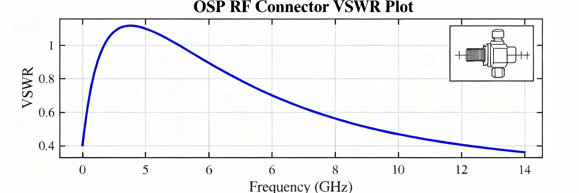
Impedance & VSWR
Return loss typically worsens above the rated range. Designers should cite datasheet VSWR values and flag omissions for lab testing using a Vector Network Analyzer (VNA).
Insulation & Fidelity
Insulation resistance in the megaohm range and dielectric breakdown voltage maintain isolation and reduce leakage, ensuring high signal fidelity in sensitive links.
Performance Testing: Methodology & Results
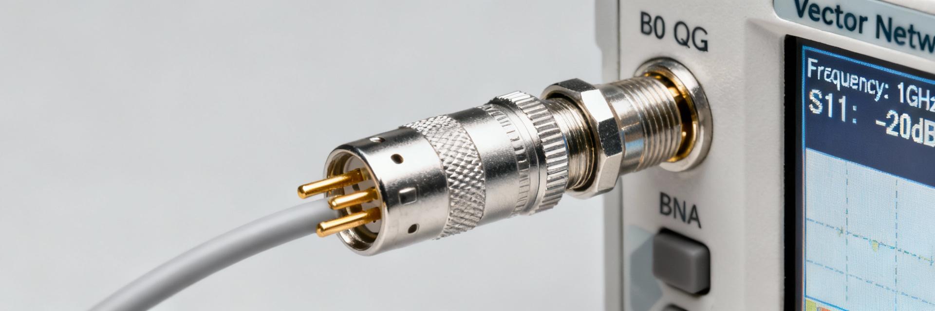
Repeatable testing validates datasheet claims and reveals assembly defects. A standard test plan uses a calibrated VNA for S11/S21, reference 50 Ω cables, and controlled environmental stress points.
Test Setup Protocol
- Calibrated Vector Network Analyzer
- High-quality 50 Ω reference cables
- Record 500–1000 mating cycles
Common Failure Modes
- Poor crimp terminations
- Plating wear after repeated cycles
- Dielectric contamination
Installation, Termination & Compatibility Guide
Crimp Best Practices
Use manufacturer-recommended crimp dies and calibrate tools periodically. Cable preparation steps—precise conductor exposure, concentric shield folding, and correct ferrule seating—affect impedance transitions significantly.
PCB & Mating Considerations
Avoid mixing impedances in a signal chain. Provide adequate panel cutout clearances and PCB mechanical reinforcement for through-hole variants to prevent pad fatigue and ensure longevity.
Summary & Key Takeaways
The 2-329063-1 is a 50 Ω BNC connector whose performance depends heavily on correct termination, assembly quality, and verification testing.
- ✓ Verify impedance and VSWR with a calibrated VNA to validate specs.
- ✓ Enforce crimp tooling and process controls to prevent signal loss.
- ✓ Use an incoming inspection checklist to catch nonconforming lots early.
- ✓ Plan replacement intervals based on mating cycles and wear.