BNC Jack Specifications: Comprehensive 50Ω Performance Guide

BNC Jack Specifications: Comprehensive 50Ω Performance Guide
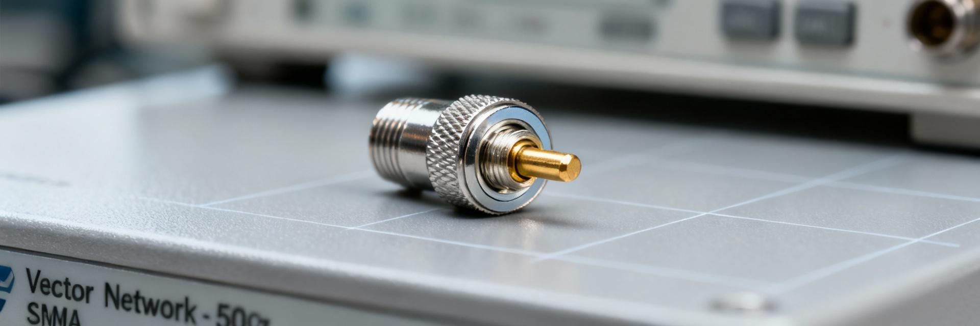
50 Ω BNC jacks remain a de facto standard on RF test benches and many instrumentation products—commonly specified for reliable performance up to ~4 GHz. Engineers evaluating connectors focus first on impedance control, return loss (S11), insertion loss (S21), and mechanical durability.
This guide translates electrical and mechanical specifications into actionable selection, test, and integration advice for engineers and technicians. It concentrates on practical spec interpretation, measurement best practices, PCB integration, and common failure modes so teams can specify, test, and procure connectors that meet system-level needs without guesswork.
Quick Reference: Essential BNC Jack Specifications
What to list on a spec sheet
Point: A concise spec sheet prevents ambiguity during procurement and test.
Evidence: Every sheet should state nominal impedance (50 ohm), frequency range, VSWR/return loss, insertion loss, DC voltage rating, RF power handling, contact and insulation resistance, mating cycles, temperature range, materials/plating, and mounting type.
Explanation: These fields allow cross-checks against S-parameter files and help buyers request guaranteed limits instead of typical curves.
| Field | Typical | Guaranteed | Units | Notes |
|---|---|---|---|---|
| Nominal Impedance | 50 | 50 ± 2 | ohm | Measured 100 MHz–4 GHz |
| Frequency Range | DC–4 | DC–4 | GHz | See S-parameter appendix |
| VSWR (max) | 1.15 | ≤1.3 | ratio | Mated, reference plane defined |
Electrical Performance: Impedance, Return Loss, and Frequency Behavior
Impedance Matching
Point: Strict 50 ohm control minimizes reflections and preserves power transfer.
Evidence: Mismatch sources include connector geometry, PCB transition discontinuities, and dielectric permittivity variance.
Explanation: Specify impedance tolerance (e.g., 50 ± 2 ohm) and require measured TDR or S11-derived impedance plots.
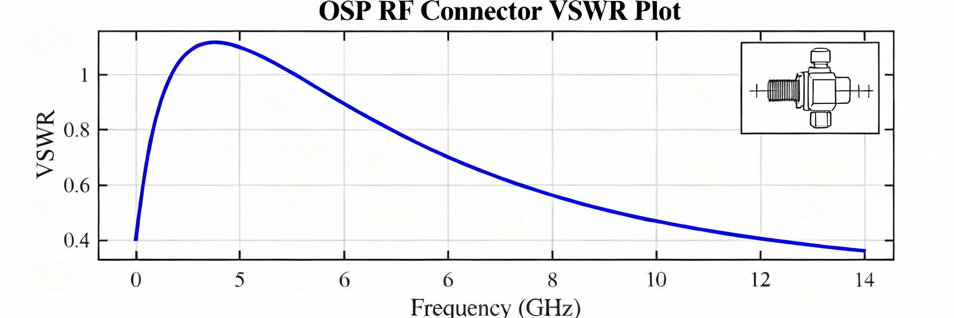
S-Parameter Analysis
Point: S-parameter curves convey usable bandwidth and mismatch severity.
Evidence: Target return loss better than 14 dB (S11
Explanation: Include measurement conditions (SOLT/TRL calibration) and clearly mark the reference plane.
Visualization: S-Parameter Magnitude Performance
Legend: Bar width represents relative signal integrity (Left: S11 | Right: S21)
Frequency Limits, Power Handling & Electrical Ratings
Usable Frequency Ranges
Usable frequency depends on mechanical tolerances and dielectrics. Most 50 ohm BNC jacks are rated to 4 GHz. Above that, geometry and surface finish dominate performance.
Voltage & Transient Safety
Specify DC and RF limits alongside peak transient handling. Require derating curves versus frequency and temperature for high-ambient applications.
Mechanical & Materials Specifications
- Materials: Conductive bodies and contacts with high conductivity (Gold plating) reduce loss.
- Dielectrics: Stable permittivity (e.g., PTFE) ensures consistent impedance.
- Durability: Specify mating cycles (500–1,000) and panel nut torque requirements.
- Environment: Account for IP ratings, vibration, and thermal cycling reliability.
Plating Integrity
Contact plating thickness directly correlates with signal longevity and wear resistance.
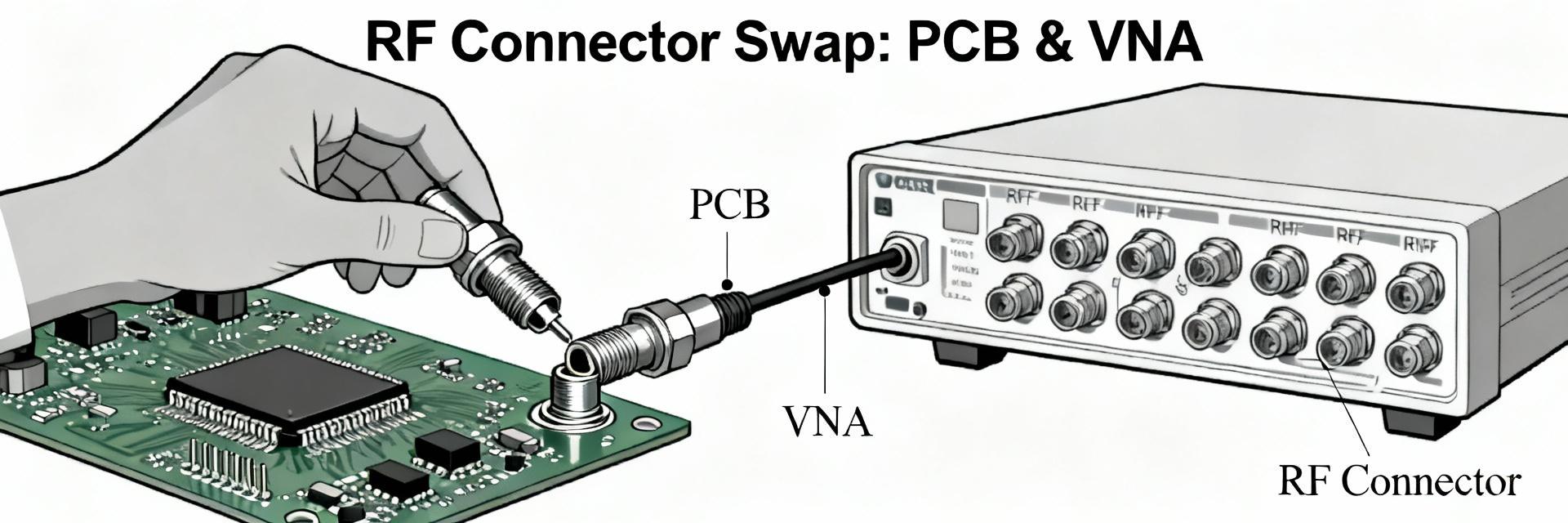
Design Integration & PCB Layout
Footprint Best Practices
Use a controlled microstrip/stripline transition. Place a perimeter ground via fence to minimize EMI. Avoid ground windows that create step discontinuities in impedance.
Mitigation: Specify mating cycles and corrosion-resistant plating to prevent mechanical failures over time.
Summary (Actionable Takeaways)
- Specify impedance and S-parameter guarantees, not just typical plots, to ensure true 50 ohm behavior.
- Request calibrated S-parameter files (S2P) with defined reference planes for meaningful comparisons.
- Include mechanical durability (mating cycles, plating, mounting) to avoid early deployment failures.
- Adopt standardized lab procedures (SOLT/TRL) and document pass/fail thresholds for qualification.