Rated to 40 GHz and designed for 50 Ω systems, the SF1211-6044-TD is often specified where minimal insertion loss and high‑frequency stability matter. This article breaks the official datasheet into clear electrical specifications, practical test procedures, and procurement checkpoints so engineers and buyers can validate parts for RF/microwave board- and fixture-level applications. For search intent capture, readers seeking a formal spec reference might look for "SF1211-6044-TD datasheet PDF" to retrieve the original measurement tables and mechanical drawings.
Background & Key Part Overview
What the part is and common use cases
PointThe component is a high-frequency coaxial interface intended for 50 Ω RF/microwave signal paths used in board-mounted interfaces and test fixtures. EvidenceThe datasheet specifies nominal 50 Ω impedance and an upper frequency rating in the tens of gigahertz. ExplanationDesigners typically choose this style of connector when preserving signal integrity up to the specified maximum frequency, using it in applications such as test jigs, high-speed RF boards, and interconnect assemblies.
Package, termination and mechanical summary
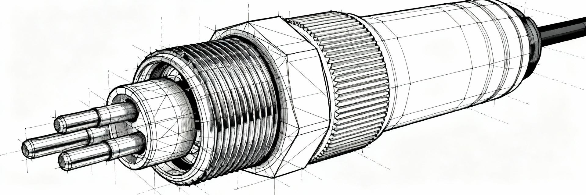
PointThe part is offered in a board-mount termination style with solderable tails and a defined gender/pin configuration. EvidenceThe datasheet lists mounting options, termination type, and recommended PCB land patterns with mechanical dimensions. ExplanationFor quick selection, use the table below to confirm termination, mating interface, and board clearance before laying out the PCB footprint to avoid mechanical interference and assembly rework.
ParameterTypical Value
Impedance50 Ω
Rated frequencyUp to 40 GHz
TerminationSolder tail / PCB mount
MountingThrough-hole / surface pad (per datasheet)
PortsSingle coaxial interface
Complete Electrical Specs — Parameters & What They Mean
Core electrical parameters to extract from the datasheet (VSWR/return loss, insertion loss, impedance, frequency range)
PointKey electrical specs to extract include impedance, nominal frequency range, VSWR (or return loss), and insertion loss across the band. EvidenceThe datasheet presents tabulated S-parameter or limit data per frequency bands and measurement conditions. ExplanationWhen reviewing those tables, note the test reference plane and whether values are reported as "typical" or "maximum" — designers should use maximum limits for margin and typical curves for modeling performance in simulations and system budgets.
PointImpedance mismatches show up as elevated VSWR or degraded return loss; insertion loss grows with frequency and connectors/adapters. EvidenceDatasheet curves typically show insertion loss in dB and VSWR as a function of frequency up to the rated maximum. ExplanationAcceptable ranges depend on system sensitivity — for many 50 Ω microwave links, maintain VSWR low enough to keep return loss above design thresholds and insertion loss within the system budget, accounting for cable and adapter contributions.
Electrical limits, environmental ratings, and derating guidance
PointEnvironmental and power handling specs (operating temperature, power rating, dielectric material) influence real-world performance. EvidenceThe datasheet lists operating temperature ranges and material notes that affect dielectric loss and mechanical stability. ExplanationDesigners must verify test conditions (temperature, fixture, calibration) stated on the datasheet — derating may be necessary where elevated temperatures or prolonged high-power exposure increase insertion loss or reduce reliability.
Test Procedures & Measurement Best Practices
Recommended lab tests to validate datasheet claims (S-parameter sweep, VSWR, insertion loss, isolation)
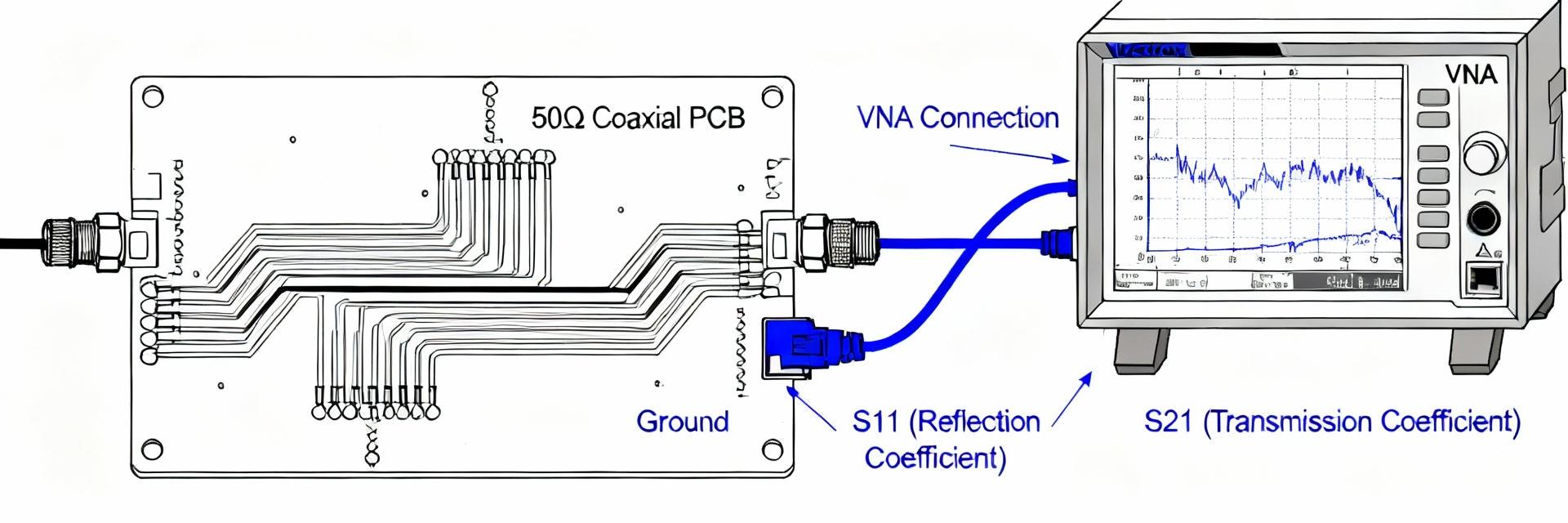
PointTo validate datasheet claims, run calibrated S-parameter sweeps for S11/S21 (return loss/insertion loss) and isolation where applicable. EvidenceBest practice uses full two-port VNA measurements with SOLT or TRL calibration to the connector reference plane. ExplanationSteps1) Select appropriate test ports and precision adapters; 2) Perform a full VNA calibration to the intended reference plane; 3) Sweep slightly beyond the datasheet frequency range; 4) Compare typical and maximum traces to datasheet values and flag deviations beyond expected tolerances (commonly a few hundredths to tenths of a dB for insertion loss at lower GHz bands).
Test fixtures, fixturing tips and reporting format
PointTest fixturing and documentation drive reproducibility and traceability of results. EvidenceThe datasheet notes whether measurements were made with specific fixtures or sample preparation. ExplanationRecord the calibration method, cable and adapter part numbers, ambient temperature, and averaging settings; present results as plots and tables with clear reference planes and note any de-embedded fixture contributions so procurement and QA can accept or reject lots based on consistent criteria.
Typical Test Results — Example Data & Interpretation
Example S-parameter plots & what they reveal (return loss, insertion loss)
PointAnnotated S-parameter plots reveal where a part tracks or diverges from datasheet curves. EvidenceExample plots should show S11 and S21 across DC–rated max frequency with markers at key bands. ExplanationInclude plots showing typical insertion loss vs. frequency and return loss; annotate features such as resonances, slope increases at high frequency, and any abrupt deviations — these annotations help pinpoint causes like contact misalignment or dielectric discontinuities.
Failure modes & troubleshooting
PointCommon failure modes include poor solder fillets, misalignment on PCB, and adapter/cable mismatches that inflate VSWR or insertion loss. EvidenceTest anomalies frequently correlate with mechanical defects or incorrect calibration. ExplanationTroubleshoot by inspecting solder joints under magnification, measuring continuity and contact resistance, repeating calibration with known-good standards, and substituting cables/adapters to isolate connector vs. cable issues.
Integration & Design Considerations
PCB footprint, mechanical clearance, and signal integrity tips
PointPCB layout, ground stitching, and clearance control parasitic inductance and stray capacitance at high frequency. EvidenceDatasheet land patterns and mechanical drawings define recommended keepouts and pad geometries. ExplanationFollow the recommended footprint, provide ground vias arrayed around the connector, maintain coplanarity during assembly, and avoid nearby routed traces that can couple into the coax interface; these measures minimize impedance discontinuities and preserve performance to the rated frequency.
Matching, adapters, and system-level impacts
PointAdapters and mating practices affect system VSWR and noise floors; use minimal transitions. EvidenceDatasheet statements about mating cycles and interface compatibility guide selection. ExplanationUse direct mating or the fewest adapters possible, ensure clean mating surfaces, torque to recommended values where applicable, and model system-level impacts by adding connector S-parameters into system simulations to predict overall VSWR and noise performance.
Procurement & Compliance Checklist
What to verify before purchase (datasheet checklist)
PointA pre-purchase checklist prevents costly mismatches between procured parts and design requirements. EvidenceVerify the exact part number, 50 Ω rating, maximum frequency, termination style, and availability of S-parameter/test reports in the datasheet. ExplanationAlso confirm RoHS/lead-free status and request sample test data or lot trace reports to ensure consistency; suggested search phrases include "SF1211-6044-TD datasheet PDF" when seeking official measurement tables and mechanical drawings.
Sample acceptance tests and QA sign-off criteria
PointDefine clear acceptance metrics for incoming inspection and lot testing. EvidenceTypical criteria include VSWR within specified limits at defined frequencies and continuity/visual inspection pass. ExplanationSet minimal acceptance thresholds (e.g., VSWR limit per datasheet band, no visible solder cold joints) and sample sizes based on lot quantity, with rejection criteria and rework procedures documented for QA sign-off and traceability.
Summary & Next Steps
PointReviewing the SF1211-6044-TD datasheet for electrical specs, test methods, and integration considerations ensures reliable system design and procurement decisions. EvidenceThe part’s 50 Ω rating and high-frequency capability make verification of VSWR and insertion loss essential for high-performance RF applications. ExplanationNext stepsdownload the official datasheet, run calibrated S-parameter tests to the declared reference plane, and apply the procurement checklist before volume acceptance to avoid field failures and ensure system performance.
Confirm impedance and rated frequency from the datasheet and verify return loss and insertion loss with calibrated S-parameters before integration; document reference plane and calibration method.
Use the provided mechanical land pattern and maintain ground stitching and clearance on the PCB to minimize parasitics and preserve high-frequency performance.
Define acceptance thresholds for incoming lots (VSWR per band, visual solder quality, and sample S-parameter traces) and require traceable test reports for procurement sign-off.
FAQ
How do I obtain the SF1211-6044-TD electrical specs in a usable format?
Request the official datasheet PDF from the part documentation portal or distributor technical pages and extract the S-parameter tables and mechanical drawings; import S2P files into your simulator where available and verify the reference plane before using the data in system models.
What test procedure should I follow to validate the datasheet S-parameters?
Use a calibrated two‑port VNA with SOLT or TRL to the connector reference plane, select precision cables/adapters, sweep slightly beyond the specified band, and record S11/S21 with averaging off (or as noted) — report both typical and maximum traces alongside calibration logs for traceability.
What are the most common causes when measurements deviate from datasheet values?
Deviations often stem from improper calibration, damaged or dirty mating surfaces, poor solder joints, or using multiple adapters that add mismatch; isolate the connector by substituting known-good cables and re-calibrating to the intended reference plane to diagnose the root cause.


