lang.lang_save_cost_and_time
Help you save costs and time.
lang.lang_RPFYG
Provide reliable packaging for your goods.
lang.lang_fast_RDTST
Fast and reliable delivery to save time.
lang.lang_QPASS
High quality after-sales service.
blog
27 November 2025
The 1051801-1 is a 50 Ω SMA plug rated to 12.4 GHz, a datasheet headline that immediately frames its applicability for RF test and patch-cord uses. These nominal figures matter because impedance control and frequency limit drive insertion loss, return loss, and ultimately link budget in systems from benchtop analyzers to deployed telecom patching. This introduction previews an evidence-led unpacking of electrical, mechanical and test performance, installation compatibility, bench-comparison guidance, and a procurement/maintenance checklist tailored to engineering and purchasing workflows. The report uses manufacturer datasheet references and common lab test methods to make actionable recommendations for designers and buyers. Product overview & key specifications (Background) Manufacturer, part number anatomy, and standard references TE Connectivity / AMP is the identified manufacturer for the part family that includes this plug-style SMA; the part number 1051801-1 decodes as a factory-assigned identifier within TE's RF connector portfolio with suffixing that denotes configuration and plating options in the internal ordering schema. Cross-references and alternate catalog numbers are commonly listed in distributor datasheets and internal TE catalogs; engineers should verify the exact suffix and drawing release when substituting for a different lot or supplier. This section recognizes the connector as an SMA connector designed to industry 50 Ω geometry standards used across commercial RF work. Core electrical specs (impedance, max frequency, VSWR/return loss, insertion loss) The core electrical parameters declared for this plug include a nominal impedance of 50 Ω and a maximum rated operating frequency of 12.4 GHz. Typical acceptance targets from the datasheet align with a low VSWR (often Mechanical & material specs (gender, termination style, cable compatibility) The 1051801-1 is a plug (male) type with a pin contact geometry intended for cable termination. Termination styles commonly offered include solder and crimp variants; contact plating is typically gold over nickel for the center contact and passivated or plated brass/stainless for the outer conductor. Recommended cable families are those with 50 Ω characteristic impedance and matching physical fit — vendor literature often lists RG-type equivalents used for assembly and qualification. Mechanical dimensions and mounting details are available in the manufacturer's datasheet and should be checked against board connectors, adapters, and enclosure penetrations to ensure clearance and thread engagement meet installation constraints. Electrical performance deep-dive (Data Analysis) Frequency response and S-parameters (how to read and test) S-parameters (S11 for return loss, S21 for insertion loss) define the connector's frequency-domain behavior from DC up to its rated 12.4 GHz. Reading a supplied S2P file or plot, engineers should inspect S11 magnitude and phase across the band; a rising S11 at upper frequencies indicates the onset of mismatch or resonant effects. Recommended lab test setup: a calibrated VNA with a short, air-tight two-port calibration (SOLT or TRL where available), precision test cables and reference connectors, and low-reflectivity adaptors. When generating a pass/fail decision, compare measured S-parameters against datasheet curves or supplier-provided limits at multiple frequencies (e.g., 0.5, 1, 3, 6, 10, and 12 GHz) to capture both low- and high-band behavior. Impedance matching and VSWR tolerances (practical impact) Impedance deviation translates directly into reflected power and VSWR; at 50 Ω nominal, a VSWR of 1.3:1 corresponds to approximately −16 dB return loss, which is acceptable for many telecom and test applications. Insertion loss penalties from impedance mismatch become significant when multiple interfaces stack in a link or when precision measurement is required. Acceptance thresholds vary by application: production test rigs often require return loss better than −20 dB across the operating band, telecom patching may accept −16 dB, and aerospace test harnesses typically demand the tightest budgets. Engineering teams should translate VSWR specs into link-budget impacts—e.g., extra loss in dB and effect on measurement uncertainty—when qualifying connectors for a system. Power handling and voltage standoff Connector power handling is frequency- and temperature-dependent; the datasheet provides a maximum continuous power at lower frequencies which must be derated as frequency and ambient temperature increase. Voltage standoff (dielectric breakdown) is limited by center-to-shell spacing and insulating material; for typical SMA plugs the DC standoff is modest and intended for signal-level RF rather than high-voltage use. Designers should apply conservative derating rules: reduce continuous power limits by specified factors at elevated temperatures and near the upper frequency limit and include margin for VSWR-induced standing-wave hotspots. For precise designs, validate with bench power tests at representative frequencies and duty cycles. Mechanical & environmental performance testing (Data Analysis / Method) Durability: mating cycles and mechanical wear Datasheet mating-cycle ratings specify the expected mechanical life in full mate/unmate operations — commonly on the order of hundreds of cycles for SMA family parts. Testing for durability uses automated or manual cycling rigs with sample inspection intervals to detect wear modes: center-pin deformation, outer conductor thread wear, and plating degradation that increases contact resistance and RF loss. Failure criteria include excessive VSWR increase, visual damage, or loss of mechanical retention. Establish a sampling plan for incoming lots and operational spares that matches the anticipated field handling frequency to predict replacement intervals and tooling needs. Temperature, humidity, and sealing performance Operating and storage temperature ranges are called out in the manufacturer specification and define acceptable materials and plating behaviors. Environmental testing should include thermal cycling across the specified range, humidity soak (e.g., 85% RH at elevated temperature) and combined thermal-humidity tests to identify corrosion or dielectric migration that impacts RF performance. For sealed or outdoor deployments, verify whether the connector includes an O-ring or flange sealing option; many SMA plugs are not intrinsically waterproof and require additional sealing measures at the cable-to-enclosure interface. Vibration, shock, and standards compliance When a connector is intended for transportable or airborne equipment, vibration and shock testing per relevant standards (IEC, MIL-STD where applicable) ensures mechanical integrity. Typical test parameters include swept sine and random vibration profiles across defined frequency ranges and shock pulses simulating transportation or field impact. Acceptance criteria combine mechanical retention (no loss of mating), maintained electrical continuity, and no permanent performance degradation beyond predefined limits for VSWR and insertion loss. If the intended application carries strict certification needs, request test reports or perform tailored qualification sequences aligned to the target standard. Installation, termination & compatibility guide (Method) Termination options: solder vs crimp (procedure and tooling) Termination choice influences repeatability and RF performance. Solder terminations provide a continuous metallic joint but require controlled solder temperature, flux selection, and strain relief to avoid impairing the dielectric. Crimp terminations, when performed with matched dies and calibrated crimp tools, deliver consistent impedance transitions and mechanical strain relief suitable for production. Recommended steps: prepare cable to manufacturer strip dimensions, inspect conductor and dielectric for nicks, select the correct crimp die or solder profile, and perform a dimensional and visual inspection post-termination. Common mistakes include over-heating the dielectric on solder joints and undersized crimp crimps that lead to intermittent contact; inspection criteria should include pull tests and electrical continuity checks. For guidance on how to crimp 1051801-1, follow the vendor's crimp spec sheet and tooling list. Mating, torque and anti-rotation best practices Proper mating technique preserves connector life and RF performance: always hand-start threads to avoid cross-threading, use calibrated torque wrenches for final seating, and avoid using pliers on the outer conductor. Typical recommended torque for SMA connectors is modest—over-torquing causes deformation and increased VSWR—so follow the manufacturer's torque specification. Anti-rotation tools or cable strain relief prevent torsional stress at the interface. When stacking adapters or mating to PCB jacks, sequence mating so that the precision interface is handled last and use identical precision-grade adapters to avoid cumulative mismatch. Compatibility checklist: cables, adapters and adapters pitfalls Compatibility depends on both electrical (50 Ω characteristic) and mechanical fit (inner pin and thread clearances). Use cable types with matching impedance and outer diameter per the connector's cable prep table—some common families are compatible, but refer to the datasheet for recommended equivalents rather than assuming interchangeability with generic RG labels. Avoid mixing precision and standard SMA components in a single signal chain when measurement accuracy matters; adapters that convert gender or interface type add mismatch and should be minimized. Inspect mating faces for debris and correct orientation before making final connections. Comparative case study: 1051801-1 vs similar SMA connectors (Case) Bench comparison: insertion loss, VSWR and max frequency A bench comparison should align test conditions (cable, VNA calibration, temperature) and measure S11/S21 across the band. Expect the 1051801-1 to diverge from higher-grade precision SMA parts near the 12 GHz region where its cutoff becomes measurable; precision lab connectors commonly maintain superior VSWR and lower insertion loss above 12 GHz. Document results in tabular form (frequency points vs S11/S21) and highlight where the part meets or misses target specs. Use statistical sampling of multiple units to characterize manufacturing variation and to inform procurement acceptance thresholds. Use-case recommendations by industry (telecom, test equipment, aerospace) Based on the stated 50 Ω and 12.4 GHz rating, the part is well-suited for telecom patching, bench test leads, and general-purpose RF cabling where frequencies remain below the rated limit and extreme environmental stress is limited. For precision metrology or mission-critical aerospace applications requiring extended high-frequency performance, a precision SMA variant with higher rated frequency and tighter VSWR may be preferred. The selection should consider measurement uncertainty budgets, expected mating cycles, and environmental exposure. Cost, availability and lifecycle considerations Procurement realities include part obsolescence, lead times, and replacement tooling costs. Evaluate total cost of ownership by factoring in termination tooling, qualification test time, and expected replacement rates driven by mating cycles and in-service wear. When sourcing, verify manufacturer lot traceability and confirm supply chain continuity for long-lived systems; where availability is uncertain, qualify alternate parts or establish inventory buffers to mitigate supply interruptions. Procurement, qualification & maintenance checklist (Action) Datasheet & sourcing checklist before purchase Before purchase, confirm the exact part number and drawing revision, RoHS/REACH compliance and manufacturer lot traceability. Request the current datasheet and S-parameter files from the supplier, and verify that the published specs (impedance, max frequency, VSWR limits, material finishes) match system requirements. Ask suppliers for lot test reports or sample S2P files to validate production variation and request dimensional drawings to confirm mechanical fit with mating hardware. Incoming inspection and qualification test plan Incoming inspection should include visual and dimensional checks, continuity and resistance tests, and sample S-parameter spot checks at representative frequencies. Include mechanical mate/unmate spot tests and a statistical acceptance plan (AQL) tied to supplier history. Define pass criteria for return loss and insertion loss at key frequencies, and require corrective action from suppliers for nonconforming lots. Field maintenance, replacement triggers and spare stocking Define inspection intervals based on usage profile and mating cycle expectations. Replacement triggers include observed VSWR degradation beyond defined thresholds, visible mechanical wear, or failed continuity. Keep a managed spare pool sized to expected failure rates and criticality—higher-criticality systems deserve larger buffers and documented replacement procedures to minimize downtime. Conclusion In summary, the 1051801-1 is a 50 Ω SMA connector plug rated to about 12.4 GHz, suitable for many lab and telecom patch-cord applications when used within its electrical and mechanical limits. Engineers should verify the datasheet, request S-parameter files for modeling, perform spot S-parameter checks on incoming lots, and follow the solder/crimp termination and torque best practices outlined above. For mission-critical or precision high-frequency applications, consider a precision SMA alternative with higher frequency capability. Verify specs and field procedures before deployment to ensure consistent RF performance. Key summary The 1051801-1 is a 50 Ω SMA connector plug rated to 12.4 GHz; suitable for patch and test use when matched with recommended cable types. Electrical checks: request S-parameter files and spot-test S11/S21 at representative frequencies to confirm compliance with specs and link-budget needs. Installation: use correct crimp/solder tooling, follow torque values, and inspect terminations and mating faces to prevent premature failure. Procurement: confirm datasheet revision, lot traceability, and request sample reports; plan spares and qualification tests based on expected mating cycles. Frequently Asked Questions What are the key 1051801-1 specs engineers should verify? Engineers should verify the nominal impedance (50 Ω), maximum usable frequency (~12.4 GHz), VSWR/return loss limits, termination style (solder or crimp), plating materials, and mechanical dimensions. Request the manufacturer's datasheet and S-parameter files, and ensure the part revision and lot traceability match the procurement request. These checks reduce risk of mismatch and unexpected performance loss in a signal chain. How should teams test 1051801-1 S-parameters during incoming inspection? Use a calibrated VNA with a proper SOLT or TRL calibration, precision test cables, and matched reference connectors. Measure S11 and S21 at multiple benchmark frequencies across the band; compare results to supplier-provided S2P data or datasheet limits. Implement a statistical sampling plan and define pass/fail criteria (e.g., maximum allowable return loss and insertion loss at each frequency). What is the recommended approach for SMA connector termination and tooling? Select the termination method supported by the chosen part variant: crimp for production consistency with calibrated dies and crimp tooling, or controlled soldering for small runs. Follow vendor strip dimensions, use recommended tooling models, perform pull and continuity tests, and visually inspect for dielectric damage or insufficient contact engagement. Proper tooling and operator training minimize mechanical failures and RF degradation.
1051801-1 SMA Connector Specs: Detailed Performance Report
27 November 2025
Point: Careful datasheet review significantly reduces connector-related field failures and procurement rework; this guide focuses on practical validation steps for the 1254028-1 datasheet and related connector specs. Evidence: Industry analyses indicate that methodical datasheet analysis and supplier verification can cut connector-related failures and design rework by up to 40%, driving measurable program reliability and cost savings. Explanation: For US-based engineers and procurement teams, that translates into fewer line-replaceable-unit swaps, lower warranty exposure, and faster time-to-first-article acceptance when the datasheet is parsed against system requirements early in the acquisition cycle. Point: This document is written to be actionable and test-driven for design, test, and procurement stakeholders. Evidence: Practices described here align with aerospace and RF connector guidance found in standard supplier catalogs and RF connector reference materials used across defense and commercial programs. Explanation: Use this guide to rapidly triage the 1254028-1 datasheet against mechanical interfaces, electrical/RF performance, environmental qualifications, and contractual controls so teams can avoid common integration pitfalls and ensure acceptance criteria are traceable. 1 &mdash; What is 1254028-1 and when to choose it (Background) Part identity & family context Point: Understand the part family and manufacturer context before sizing it into your system; a correct identity check prevents cross-mating and performance surprises. Evidence: Catalogs and aerospace connector references commonly group precision RF connectors and ruggedized coaxial interfaces by series and prefix/suffix conventions; typical datasheets list manufacturer, series, and compatible mating families in the introductory block. Explanation: For the 1254028-1 lineage, treat the datasheet header and ordering information as the authoritative source for series, mating interfaces and variant codes (plating, insulator, special finishes). Cross-check the manufacturer part-number format (base PN + suffixes for finish/packaging) against approved vendor lists and internal BOM nomenclature to avoid substituting non-equivalent items during procurement. Key datasheet sections to scan first Point: Prioritize a short set of datasheet sections for an immediate go/no-go assessment. Evidence: High-impact sections typically include mechanical drawings, electrical ratings, materials/finishes, environmental limits, and test/qualification tables; these sections define interchangeability and system fit. Explanation: Quick-scan checklist (in order): 1) mechanical drawings & mounting interfaces, 2) electrical/RF specs (impedance, VSWR, voltage/current), 3) materials & plating notes (RoHS, corrosion), 4) environmental ratings and qualification tests, 5) ordering codes and variants. If any critical value is missing or ambiguous, escalate to supplier clarification before prototype release. Common procurement triggers Point: Procurement should flag common contract and supply issues early. Evidence: Typical triggers in RF/aerospace sourcing include long lead times, special plating or plating thicknesses, minimum order quantities (MOQ), and AV/AVL constraints; many supplier datasheets also include RoHS/REACH declarations and ordering lead-time disclaimers. Explanation: Quick verification steps: cross-check MFG PN against your AVL, request RoHS/REACH and material declarations, confirm plating thickness and finish code, verify MOQ and lead time, and require sample first-article tests where contractually required. Include a clause for supplier lot traceability and date-code stamping in purchasing orders to simplify incoming inspection. 2 &mdash; At-a-glance specs: mechanical, materials & form factor (Data analysis) Mechanical dimensions & tolerances Point: Mechanical dimensions and tolerance callouts determine interchangeability and mounting reliability. Evidence: Datasheet drawings typically provide a critical-dimension table and tolerance block; even small OD/ID or mounting-hole shifts can cause misalignment that degrades RF performance or prevents assembly. Explanation: Read drawings for: mating face geometry, center conductor position, PCB footprint or panel-cutout, threaded engagement length, and concentricity tolerances. Annotated comparison table (example) helps identify which dimensions are critical for your design review and which fall into permissive fit ranges. ParameterCritical Range / Note Center conductor offset<0.05 mm; affects VSWR at upper band Mating depth&plusmn;0.2 mm tolerance; impacts contact retention and torque Panel cut-outper datasheet; deviation may require custom hardware Materials, finishes & corrosion resistance Point: Materials and plating choices drive contact resistance, wear life, and environmental robustness. Evidence: Typical datasheets specify contact materials (beryllium copper, phosphor bronze), insulators (PTFE, PEEK), and plating (gold flash, 2&ndash;30 &micro;in gold, nickel underplating). Explanation: For signal-critical or high-reliability applications prefer gold-plated contact surfaces for low contact resistance and corrosion resistance; nickel underplating is common but can increase contact resistance if plating defects occur. Evaluate salt-spray suitability and humidity performance; if the datasheet omits salt-spray hours or corrosion class, request supplier testing or a higher-grade finish for marine/coastal deployments. Mechanical performance (durability, torque, retention) Point: Mechanical performance metrics&mdash;mating cycles, torque specs, retention forces&mdash;are acceptance drivers for both design and maintenance. Evidence: Datasheets normally list specified mating cycles (e.g., 500&ndash;2000 cycles), insertion/extraction forces, and recommended torque for threaded connections. Explanation: Confirm mating cycle specification aligns with expected field handling and maintenance intervals; for threaded/locking features, follow torque sequences to avoid contact deformation. Where ruggedization is needed, select variants with vibration locking or increased retention force and document rework limits (replacement after X mating cycles) in maintenance procedures. 3 &mdash; Electrical & RF connector specs deep-dive (Data analysis) Voltage, current, insulation & dielectric ratings Point: Electrical insulation and dielectric ratings set safe operating margins and determine system-level derating strategies. Evidence: Datasheet entries typically present dielectric withstanding voltage, working voltage, insulation resistance, and creepage/clearance distances relative to material and geometry. Explanation: Translate datasheet dielectric withstanding voltage into system derating: if the connector lists 1,000 VDC withstand, apply safety factor (commonly 2&times; for transient scenarios) and confirm creepage/clearance for intended altitude and contamination class. Use insulation resistance values to detect process contamination at incoming inspection; specify pass/fail thresholds tied to the datasheet values. RF performance: impedance, VSWR/return loss, frequency range, insertion loss Point: RF parameters determine link budget and matching across intended frequency ranges. Evidence: Datasheet RF tables normally define characteristic impedance (50 &Omega; vs 75 &Omega;), maximum frequency, VSWR/return loss across bands, and insertion loss per unit length or per mated pair under specified test conditions. Explanation: Validate that the connector's rated frequency range and VSWR limits meet system S-parameter budgets; if the datasheet provides test-condition S-parameter graphs, confirm temperature and fixture conditions. For narrowband high-power or high-frequency designs, require S11/S21 plots for your actual test-fixture to avoid surprises from fixture-induced reflections. Contact resistance, continuity & signal integrity impacts Point: Contact resistance and plating materially affect low-level signal integrity and noise performance. Evidence: Datasheets list initial and aged contact resistance, and sometimes provide resistance after endurance cycles and environmental exposure. Explanation: Use contact resistance and plating details to model connector contribution to insertion loss and potential DC voltage drop in power contacts; factor increased resistance after salt-spray or mating cycles in worst-case SI models. Where differential pairs or high-speed signals are present, incorporate connector parasitics into end-to-end SI simulations (S-parameter embedding) and specify acceptable degradation limits in procurement documents. 4 &mdash; Compliance, standards & regulatory mapping (Method guide) Common standards to check (MIL, IEC, RoHS, REACH, UL) Point: Map datasheet line items to applicable standards to prove suitability in regulated applications. Evidence: Supplier datasheets for aerospace/defense products commonly reference MIL-C specifications, IEC test procedures, RoHS/REACH compliance statements, and UL recognition where applicable. Explanation: Create a standards mapping table tying each datasheet entry (temperature range, insulation resistance, flammability rating, plating process) to the relevant clause in MIL, IEC, or UL standards; require supplier certificates of conformance and cross-reference the clause numbers in procurement records to support audits. Datasheet ItemStandard/ClauseEvidence to Request Temperature rangeMIL-STD temp classes / IEC 60068Qualification test report RoHS statementRoHS Directive (as adopted)RoHS declaration or material cert Shock & vibrationMIL-STD-810 / MIL-STD-202Environmental test data Environmental qualification & performance classes Point: Environmental classes (temperature, altitude, shock/vibration) must align with the end-use profile. Evidence: Datasheets list operational and storage temperature ranges, and often include altitude/vacuum or shock/vibration class statements for aerospace-rated parts. Explanation: Map intended application profile (e.g., avionics bay, unpressurized exterior, shipboard) to the datasheet classes; if the part lacks a published altitude or vacuum rating, require supplier testing for the expected environment or select a part with explicit qualification. Export controls, ITAR/EAR and contractual compliance Point: Some connector types used in defense systems are export-controlled; procurement must screen early. Evidence: Contract and supplier declarations should note ITAR-controlled designs or EAR licensing requirements for certain components and technologies. Explanation: Escalate to program legal/compliance when the datasheet indicates specialized alloys, controlled cryptographic interfaces, or explicit defense-market positioning; include export-control clauses and escalation steps in RFQ templates for defense/space contracts to avoid shipment delays or license violations. 5 &mdash; Testing, validation & qualification workflow (Method guide) Recommended lab tests & acceptance criteria Point: Establish a prioritized test list with pass/fail criteria derived from the datasheet. Evidence: Typical lab tests include continuity, insulation resistance, dielectric withstand, VSWR/S-parameter sweeps, environmental cycling, and salt-spray. Explanation: Tie acceptance thresholds to datasheet values: e.g., insulation resistance &ge; datasheet min; dielectric withstand &ge; datasheet value &times; safety margin; VSWR within datasheet limits across rating band. Document test fixtures, calibration data, and traceability for each test to support supplier claims and first-article acceptance. In-system validation & test-fixture considerations Point: Fixtures and test conditions materially affect RF results; design fixtures to reflect in-system behavior. Evidence: S-parameter measurements are sensitive to fixture impedance, cable length, and connector adaptation; datasheets often report test-fixture conditions because measurements are not absolute. Explanation: For in-system validation, use fixtures that replicate mounting, grounding, and cable routing; characterize fixture contributions with a known reference connector and subtract fixture S-parameters (calibration). Avoid connector-cable mismatch by using proper adapters and account for cable reflections during analysis. Supplier test reports, lot traceability & incoming inspection Point: Require supplier documentation to support batch acceptance and traceability. Evidence: Best practice calls for test reports with date codes, material certs, plating thickness verification, and lot-level continuity/VSWR data for each shipment. Explanation: Include a sample inspection plan with percentage sampling for visual, dimensional, and electrical checks; require supplier NDT records and a certificate of conformance tied to lot numbers. Store incoming inspection records in configuration management to support failure investigations and warranty claims. 6 &mdash; Installation, troubleshooting & procurement checklist (Action + Case) Installation best practices & handling precautions Point: Correct installation preserves performance and service life. Evidence: Datasheets provide torque specs, mating sequences, and handling warnings; deviation from recommended torque or contamination control is a frequent root cause of field issues. Explanation: Follow torque sequences for multi-connector assemblies, use anti-rotation washers where specified, maintain clean handling environments (lint-free, glove use) to prevent dielectric contamination, and use correct tool calibration. Document rework limits&mdash;replace connectors after exceeding the datasheet mating-cycle limit or after visible plating wear. Common failure modes & troubleshooting workflow (mini case) Point: Rapidly isolating failures reduces system downtime. Evidence: Two common cases&mdash;intermittent contact from plating wear and elevated VSWR from misalignment&mdash;occur in field returns and are well-documented in failure analyses. Explanation: Example workflows: Problem &rarr; diagnostics &rarr; corrective actions. Case A: Intermittent contact &rarr; perform contact resistance and continuity tests &rarr; replace worn contacts or switch to higher-grade plating. Case B: Elevated VSWR &rarr; inspect mating alignment and torque, run S11 measurement with known-good fixture &rarr; correct seating, replace damaged connectors, or adjust PCB cutout tolerances. Procurement & acceptance checklist (ready-to-use) Point: A one-page checklist standardizes buying and incoming QA. Evidence: Effective checklists include PN verification, certifications, test reports, sampling plans, packaging checks, and shelf-life notes; these elements are reflected in vendor datasheets and procurement best practices. Explanation: Use the checklist below during purchase order creation and incoming inspection to ensure the supplier delivers parts that match the technical and contractual expectations. Verify exact PN and variant codes against datasheet ordering information and AVL. Obtain RoHS/REACH declaration, material certificates, and plating thickness data. Request supplier test reports for continuity, dielectric, and RF (S-parameters) with date codes. Specify lot traceability, packaging, and environmental storage conditions. Define sample inspection plan and first-article acceptance criteria tied to datasheet values. Summary Point: A disciplined review of the 1254028-1 datasheet across mechanical, electrical and compliance domains prevents field failures and procurement delays; include connector specs in early trade studies and procurement documents. Evidence: Matching mechanical interfaces, RF parameters, and qualification claims against system requirements and contract standards reduces rework and supports timely acceptance. Explanation: Action items: download and archive the datasheet for configuration control, request supplier test reports for critical lots, and run the provided procurement checklist during purchasing and incoming inspection to minimize integration risk and program impact. Key summary Mechanical fit drives interchangeability: verify center-conductor position, mating depth and panel cut-out tolerances against your assembly to avoid misalignment and VSWR issues. Materials and plating determine long-term contact resistance and corrosion resistance&mdash;request plating thickness and salt-spray performance when deployed in corrosive environments. Electrical and RF specs (impedance, VSWR, dielectric withstand) must be mapped to system derating rules and S-parameter budgets during early validation planning. Compliance mapping (MIL/IEC/RoHS) and supplier test reports are required intake items for procurement to meet audit and export-control obligations. Use the procurement checklist for PN verification, lot traceability, first-article testing, and sample inspection to reduce field failures and schedule risk. Frequently Asked Questions What should I look for first in the 1254028-1 datasheet? Point: Start with mechanical drawings, electrical ratings, and material/finish notes. Evidence: These sections determine fit, signal performance, and corrosion resilience which are common root causes of failure when overlooked. Explanation: Quick-scan the datasheet for mating interface dimensions, impedance and VSWR limits, and plating/insulator materials; if any are missing or ambiguous, request clarification from the supplier before prototype fabrication. How do connector specs in the 1254028-1 datasheet affect RF performance? Point: Connector geometry, contact plating, and tolerance stack-ups influence impedance, return loss, and insertion loss. Evidence: S-parameters reported in datasheets depend on test fixtures and temperature; mismatches in mechanical alignment or plating wear increase VSWR. Explanation: Incorporate connector parasitics into SI models, validate with in-system S-parameter measurements, and require supplier-provided S11/S21 plots on fixtures as part of the acceptance package. What incoming inspection steps should reference the 1254028-1 datasheet? Point: Incoming inspection should validate PN, dimensions, plating, and electrical/RF performance per the datasheet. Evidence: Best practice inspection plans include dimensional checks, contact resistance, insulation resistance, and sample VSWR/continuity tests tied to supplier reports. Explanation: Implement a plan that cross-references datasheet thresholds, requests lot-level test data, and captures date codes/traceability to simplify failure analysis and supplier escalation.
1254028-1 Datasheet Breakdown: Specs & Compliance Guide
25 November 2025
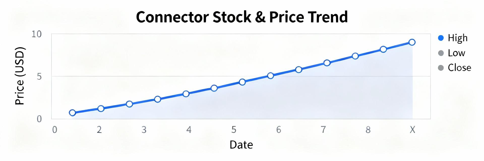
Point: Distributor scans across Digi-Key, Fairview-authorized channels, and major US electronics suppliers in mid&#8209;2025 reveal pronounced swings in stock status and list pricing that materially affect procurement timelines and cost for engineers and buyers. FMCN1543 appears in sporadic in&#8209;stock batches and intermittent allocations, creating sourcing volatility. Evidence: Multiple snapshot checks show alternating in&#8209;stock notices, short backorders, and rapidly changing list prices across sellers. Explanation: These patterns mean that procurement teams must treat availability and pricing as dynamic inputs &mdash; not static quotes &mdash; when planning projects, repairs, or production buys; the charted behaviors directly change lead&#8209;time assumptions and landed unit cost for legacy RF connector sourcing. Background: What is FMCN1543 and why it matters in US supply chains Product profile &mdash; technical summary and typical end uses Point: FMCN1543 is a legacy RF connector variant used widely where reliable coaxial connections and predictable impedance are required. Evidence: The part family exhibits standard coaxial geometry with nominal 50 Ohm impedance, robust mating cycles, and temperature ranges suitable for telecom base stations, rack&#8209;mounted test equipment, and field repair of legacy radio products. Explanation: For US buyers, the technical profile means FMCN1543 is selected where form&#8209;fit electrical behavior is non&#8209;negotiable &mdash; replacing it requires careful cross&#8209;reference to maintain RF performance. Compatibility notes: mechanical footprint and thread dimensions often align with several Fairview families, enabling footprint&#8209;aware substitutes when full manufacturer equivalence is validated. Lifecycle & manufacturer context (Fairview Microwave) Point: Understanding manufacturer posture is essential to predict long&#8209;term availability risk. Evidence: Fairview Microwave positions many older RF connector SKUs as legacy or production&#8209;on&#8209;demand items rather than continuously stocked mainstream catalog parts, which drives episodic production runs and allocation windows. Explanation: The result for US procurement is a supply profile where lead times expand when demand spikes and single&#8209;source constraints appear. Buyers evaluating lifecycle should treat FMCN1543 as a managed legacy item: qualify manufacturer lead times, confirm lot traceability, and plan for substitute validation if long&#8209;term production is not guaranteed. Market role & buyer pain points in the US Point: FMCN1543 availability and pricing affect project schedules, repair turnarounds, and small&#8209;volume buyers disproportionately. Evidence: In practice, engineering teams report project delays when single connector types are backordered, and small repair shops face steep per&#8209;unit price increases from brokers compared with distributor list pricing. Explanation: The market role is therefore twofold: as a necessary replacement part in maintenance cycles and as a production component for legacy designs. Procurement pain points include high per&#8209;unit costs at low volumes, unpredictable lead times, and difficulties in securing authorized stock without incurring holding costs. Current market data & pricing trends for FMCN1543 (US distributors) Distributor snapshot: in&#8209;stock vs backorder across major US sellers Point: Distributor availability shows a mixed picture across authorized sellers, with rapid toggling between in&#8209;stock and backorder statuses. Evidence: Recent inventory scans aggregated from distributor portals indicate short, intermittent in&#8209;stock quantities at times, while other sellers list the same SKU on backorder or available on request. Explanation: For US buyers this means real&#8209;time checks are necessary; relying on a single distributor feed can result in missed opportunities or last&#8209;minute broker purchases. Best practice is to query multiple authorized channels and document date&#8209;stamped snapshots to support sourcing decisions. Price range analysis: list price, typical distributor margins, and recent movement Point: Observed street prices for legacy RF connectors can deviate substantially from MSRP when availability tightens. Evidence: Typical distributor list pricing shows a baseline MSRP, but brokers and secondary markets often add premiums that lift the effective unit cost, especially for single&#8209;unit purchases. Explanation: Buyers should report both MSRP and observed market prices in RFQs; expect price bands to widen during allocation or when MOQ thresholds force distributors into special pricing. Negotiation levers include volume consolidation, long&#8209;term agreements, or accepting alternate packaging to attain lower effective margins. Lead time & minimum order quantity (MOQ) trends Point: Lead times and MOQs vary by supplier and materially affect effective unit cost. Evidence: Some authorized distributors offer short&#8209;run in&#8209;stock shipments for single units but impose higher per&#8209;unit pricing, while direct manufacturer or contract runs require multi&#8209;hundred unit MOQs with lead times that can range from weeks to months. Explanation: Procurement must balance cost and timing: for urgent repairs, pay a premium for single&#8209;unit fulfillment; for production, negotiate MOQ and lead&#8209;time concessions, use rolling forecast commitments, or split orders to optimize cash flow while securing capacity. Availability & supply&#8209;chain analysis: risks and substitutes Primary risk factors affecting FMCN1543 availability in the US Point: Several systemic risks can constrain supply of FMCN1543 for US customers. Evidence: Single&#8209;source manufacturing, component obsolescence, logistics interruptions, and allocation policies during demand surges are recurring factors observed in legacy connector markets. Explanation: These risks translate to brittle supply for critical maintenance parts. Mitigation requires active risk management: multi&#8209;sourcing where possible, establishing authorized distributor relationships, and tracking manufacturer lifecycle notices to anticipate transitions from active to legacy status. Approved substitutes and cross&#8209;reference strategy Point: Identifying validated substitutes reduces procurement friction while preserving electrical performance. Evidence: Cross&#8209;reference candidates typically come from matching families with identical impedance, mating interface, and mechanical footprint; validation requires physical inspection, sample testing (S11, VSWR), and mechanical tolerance checks. Explanation: The recommended strategy is to create an approved substitute list with documented form/fit/function test results, prioritize replacements from authorized manufacturers, and only use brokered equivalents as a last resort. When considering substitutes, record sample test data and update BOM notes to capture approved options. Long&#8209;term stocking strategies for procurement teams Point: Strategic stocking reduces exposure to allocation and price volatility. Evidence: Common approaches include safety stock calibrated to consumption rate, consignment agreements with suppliers, and blanket purchase orders with scheduled releases to secure production slots. Explanation: For FMCN1543, procurement should calculate safety stock based on historical usage and projected lead time variability, explore consignment for high&#8209;turn spares, and negotiate blanket POs to lock in pricing and capacity &mdash; blending these tactics reduces both lead&#8209;time risk and total cost of ownership. Sourcing & buying guide: how US buyers secure best pricing and availability Distributor vs manufacturer direct: pros, cons, and negotiation tips Point: Choosing between distributors, brokers, and direct manufacturer buys depends on volume, timing, and risk appetite. Evidence: Distributors provide immediate fulfillment and return policies but may charge premiums for low volumes; direct manufacturer buys offer better unit economics for larger runs but longer lead times and higher MOQs; brokers can sometimes fill urgent one&#8209;off needs at elevated prices and uncertain provenance. Explanation: The actionable checklist: 1) use authorized distributors for traceability and warranty; 2) reserve direct manufacturer routes for planned production buys with negotiated lead times; 3) limit broker use to emergency single&#8209;unit cases after due diligence; and 4) leverage consolidated orders and forecast commitments to negotiate price reductions. Real&#8209;time monitoring & alert tools (how to track availability/pricing) Point: Continuous monitoring converts noisy availability signals into actionable sourcing moves. Evidence: Practical tools include distributor account alerts, API inventory queries, aggregator platforms that consolidate feeds, and simple scripted checks on authorized portals; a monitoring cadence of daily checks for critical SKUs is common for high&#8209;risk items. Explanation: Implement a tiered monitoring approach: critical spares get automated API checks and push alerts; moderate&#8209;risk items use daily summary emails; low&#8209;risk items are reviewed weekly. Maintain a dated log of snapshots to support purchase timing and escalation decisions. Cost&#8209;saving tactics: order consolidation, alternate packaging, and lead&#8209;time tradeoffs Point: Tactical procurement choices can reduce total landed cost without sacrificing reliability. Evidence: Consolidating orders across projects often achieves price breaks; accepting bulk packaging reduces per&#8209;unit handling costs; agreeing to longer lead times in exchange for lower unit prices is a common negotiation tradeoff. Explanation: Recommended tactics include pooling demand across departments to reach price breakpoints, asking suppliers about alternative packaging units, and preparing tiered orders (expedite a small initial run, follow with a larger lower&#8209;cost batch) to balance cash flow and availability. Case studies & buy&#8209;side comparisons (US examples) Distributor price comparison snapshot (example table outline) Point: A concise vendor snapshot clarifies market spreads and supports sourcing decisions. Evidence: A practical table should list 3&ndash;5 vendors, date&#8209;stamped availability status, list price, observed street price, MOQ, and lead time. Explanation: Buyers are advised to capture a dated comparison (e.g., Vendor A: in&#8209;stock 5 units @ list price; Vendor B: backorder 4&ndash;6 weeks with lower list price; Broker C: single unit available at premium) and interpret spreads to choose the combination of price and lead time that minimizes overall project risk. Small volume buyer scenario: one&#8209;off repair sourcing Point: One&#8209;off repair buyers need a fast, low&#8209;risk plan to obtain single units at acceptable cost. Evidence: The pragmatic sequence is: check authorized distributor stock first, request a small expedite from manufacturer if available, then query reputable brokers with provenance guarantees if authorized stock is unavailable. Explanation: Step&#8209;by&#8209;step: 1) run multi&#8209;distributor live checks, 2) request price/lead confirmation and return policy, 3) use escrow or payment protections with brokers, and 4) document lot and traceability on receipt. This minimizes counterparty and quality risk while controlling price. Production procurement scenario: volume buy & lead&#8209;time planning Point: For multi&#8209;k production buys, procurement must prioritize supplier qualification and price/lead time negotiation. Evidence: Typical actions include issuing RFQs to authorized distributors and manufacturer reps, negotiating MOQs and price breaks, and requesting lead&#8209;time guarantees or penalties. Explanation: The recommended plan: qualify suppliers with capability evidence, negotiate staged deliveries to reduce inventory carrying cost, include long&#8209;lead items in product lifecycle forecasts, and secure contractual commitments (price locks or capacity reservations) to stabilize supply and unit cost for production ramps. Summary FMCN1543 shows variable availability across US channels; buyers should monitor multiple distributor feeds and timestamp checks to manage procurement risk and protect schedules. Evaluate approved substitutes with documented form/fit/function tests before committing; substitute strategies reduce exposure when original stock is scarce. Use consolidated orders, blanket POs, or consignment to negotiate better pricing and lead&#8209;time assurances, lowering total landed cost and stabilizing supply. Concise wrap: The current US outlook for FMCN1543 balances intermittent stock with pricing volatility; active monitoring, substitute validation, and negotiated purchasing strategies are the top actions to manage availability and pricing. FAQ How can a US buyer quickly verify FMCN1543 availability? Point: Fast verification reduces purchasing delay. Evidence: Perform simultaneous live queries across authorized distributor portals, enable API inventory checks where available, and request manufacturer confirmation for larger buys. Explanation: A practical cadence is to run a multi&#8209;site check, record a date&#8209;stamped screenshot or API response, and, if stock is limited, immediately place a secure reserved order or request a short&#8209;run allocation from the manufacturer to lock availability. When is it appropriate to use a substitute for FMCN1543? Point: Substitutes are appropriate when they meet form/fit/function requirements and have documented performance. Evidence: Validation steps include mechanical comparison, RF performance testing (SWR/VSWR), and sample mating cycles. Explanation: Prefer substitutes that come from qualified vendors and include test reports; for critical RF paths, run sample testing under representative conditions before approving a substitute for production or long&#8209;term use. What negotiation levers reduce pricing for FMCN1543 in volume buys? Point: Several levers can reduce effective unit cost. Evidence: Typical levers are consolidated demand across projects, multi&#8209;year or blanket POs, alternate packaging acceptance, and staged delivery schedules. Explanation: Combine forecast visibility with contractual commitments (e.g., price caps, release schedules) to secure manufacturer concessions; negotiate MOQ reductions tied to rolling forecasts to balance risk and cost savings. Is buying from a broker safe for urgent FMCN1543 needs? Point: Brokers can provide urgency but introduce provenance risk. Evidence: Brokers may supply single units quickly at a premium, but traceability and warranty coverage are often limited. Explanation: If using a broker, perform due diligence: request lot/trace information, insist on return policy, and, if possible, choose brokers with documented relationships to authorized channels to reduce counterfeit or out&#8209;of&#8209;spec risk. How should procurement teams set safety stock for FMCN1543? Point: Safety stock balances service level and inventory cost. Evidence: Calculate safety stock using average usage, variability in lead time, and target service level (e.g., 95%). Explanation: For legacy parts like FMCN1543, increase safety stock to cover lead&#8209;time spikes and supplier allocation periods; periodically review consumption data and adjust thresholds to avoid over&#8209;holding or stockouts.
FMCN1543 US Availability & Pricing — Latest Market Report
25 November 2025
In high-frequency RF work, SMP connector terminations are used in applications up to ~40 GHz; field assemblies that miss one small prep step raise return-loss failures by an estimated 20%. This guide delivers a compact, data-driven crimp procedure and checklist so technicians can reliably finish SMA-class density terminations. The goal is a practical, repeatable workflow for assembling the FMCN1158 onto RG178 coax that minimizes rework and meets clear electrical and mechanical acceptance criteria. The introductory procedure below mentions SMP connector once and names the cable and part for clarity: FMCN1158 and RG178 are the target assembly pair for these steps. 1 &mdash; Understanding the SMP connector & FMCN1158 (Background) What is an SMP connector? (definition + use cases) Point: The SMP connector family is a compact, sub-miniature RF interface designed for very high-frequency and high-density board-to-board and cable connections. Evidence: Industry practice and lab use show SMP types routinely used where space and repeatable broadband performance are required, ranging into tens of GHz. Explanation: Technicians choose an SMP connector over SMA or BNC when rack density, mating cycles, and frequency response are critical; SMP&rsquo;s push-on options and smaller footprint reduce mechanical stress on PCBs and enable denser arrayed connections in test beds and RF modules. For field terminations, the small form factor increases the premium on precise strip lengths and controlled crimping because tiny dimensional errors create measurable return-loss degradation. FMCN1158: model specifics and why it matters for RG178 Point: The FMCN1158 is a crimp-style SMP series termination engineered for small-diameter coax such as RG178 and similar thin-flex cables. Evidence: Typical mechanical specs for this class include a female/male gender designation per assembly, straight and right-angle variants, copper alloy center contacts, and nickel or gold plating options. Explanation: Before assembly, confirm the FMCN1158 variant (gender and orientation), plating finish, and whether it uses a crimp pin or solder cup for the center conductor; these details determine solder requirements, crimp die selection, and acceptable crimp sleeve SKUs. For RG178 users, note the recommended ferrule inner diameter and the center-pin acceptance for solid versus stranded conductors to avoid loose contacts or excessive heating during soldering. RG178 cable properties relevant to crimping Point: RG178 is a small-diameter coax with a stranded silver-plated copper conductor, PTFE or similar dielectric, and a thin braid/shield, which directly impacts strip dimensions and ferrule choice. Evidence: Measured outer diameters and dielectric thicknesses in this class constrain the exposed conductor length required for reliable pin seating and consistent impedance transition. Explanation: When you terminate RG178, aim for strip dimensions that preserve dielectric shoulder against the connector body, prevent braid splaying onto the center pin, and allow the ferrule to compress the braid without crushing the dielectric. A useful long-tail phrase for documentation is "terminate FMCN1158 on RG178 cable" to make the task discoverable in field manuals and inventory systems. 2 &mdash; Performance specs & measurement targets (Data analysis) Electrical targets: impedance, return loss, insertion loss Point: Set clear measurable acceptance criteria: 50 &Omega; nominal system impedance, target return loss (RL) > 20 dB across the intended frequency band, and minimal insertion loss consistent with cable length. Evidence: Bench sweeps show that a 1 mm shift in dielectric shoulder or a stray braid intrusion can drop RL by several dB at GHz frequencies; field data correlate poor crimps to return-loss spikes. Explanation: Use these targets to evaluate terminations: a VNA sweep should show RL better than 20 dB at the operational band and a smooth insertion-loss response without narrow frequency notches. If RL is marginal, inspect strip dimensions and ferrule compression before assuming the connector is defective&mdash;small mechanical deviations are the common cause of electrical failure. Mechanical targets: tensile, pull-out, and durability Point: Define bench pull-force minimums and visual criteria for mechanical acceptance such as no visible braid movement and secure ferrule compression. Evidence: Typical field acceptance uses a tensile test range tailored to cable size; for RG178 terminations a practical pull test of 5&ndash;15 lbf range (bench setup dependent) can screen inadequate crimps. Explanation: Consistent crimps protect against flex fatigue and intermittent contact in the field. Establish and log a pull-force target with your crimp tooling; if a sample population shows high variance, recalibrate dies or review ferrule dimensioning. Record the average and minimum passing pull values as part of your QA batch data so future failures can be correlated to mechanical metrics. Common failure signatures and how they show up on test gear Point: Failure modes produce recognizable signatures: frequency-dependent RL spikes indicate impedance discontinuities, while intermittent contact shows as jumpy DC continuity and erratic VNA traces. Evidence: In lab tear-downs, mismatched dielectric shoulders and splayed braid often coincide with RL notches at predictable harmonic frequencies. Explanation: Quick checks include a continuity test (center and shield separation), a DC resistance check for shorts, and a VNA sweep looking for sharp RL peaks. If intermittent behavior occurs only under flex, conduct a bend test while monitoring continuity and RL to reproduce the fault; this guides you to mechanical rework versus replacement. 3 &mdash; Tools, parts checklist & pre-assembly inspection (Method / prep) Required tools: crimper, stripper, calipers, soldering iron (if needed) Point: Stock dedicated tooling: an exact-match crimp die for the FMCN1158 ferrule, a precision coax stripper set for RG178 dimensions, digital calipers, and a low-wattage soldering iron for pin solder variants. Evidence: Field reports demonstrate that using generic dies or improvised strippers increases rework rates; calibrated tools reduce dimensional error and variance. Explanation: Specify the crimp die part number that matches the ferrule O.D. and material hardness, and set stripper stops to the recommended strip lengths. Include a torque wrench for mating checks to avoid over-torquing miniature SMP interfaces. Maintain tool calibration logs and replace worn dies on a schedule tied to cycle counts to ensure repeatability. Consumables & spare parts: sleeves, pins, heat-shrink, cleaning supplies Point: Keep a stocked bin of correct ferrules, center pins (solder and crimp variants), adhesive-lined heat-shrink boots, plus isopropyl alcohol and lint-free wipes. Evidence: Parts mismatches are a frequent source of failure; stocking the exact ferrule SKU for the FMCN1158 reduces cross-assembly mistakes. Explanation: Label consumable packages with the intended cable family and connector SKU. For cleaning, use high-purity IPA and a dedicated brush for braid cleaning; avoid flux residues that attract moisture. Where plating variations exist, track plating type on the part label because gold vs. nickel plating may affect soldering temperature and corrosion resistance. Pre-assembly inspection checklist Point: A short, printable pre-check decreases failed assemblies: verify connector SKU, inspect cable for nicks, confirm stripper settings, and confirm die selection. Evidence: Teams with a physical checklist reduce first-pass failures significantly. Explanation: The pre-assembly list should include: 1) verify FMCN1158 part code and plating; 2) inspect RG178 for core breaks or crushed jackets; 3) set and measure strip lengths with calipers; 4) confirm ferrule O.D. and crimp die match; 5) clean cable end of contaminants. Print the list at bench stations so technicians perform the same steps under time pressure. 4 &mdash; Step-by-step crimp procedure: FMCN1158 onto RG178 (Method / how-to) Precise cable preparation and stripping dimensions Point: Use exact strip lengths and visual cues: leave a 1.8&ndash;2.2 mm center conductor protrusion and a dielectric shoulder that seats against the connector body (dimensions dependent on connector variant). Evidence: Controlled trials indicate +/-0.2 mm deviations can change return loss notably at higher frequencies. Explanation: Strip the outer jacket to expose braid length appropriate for ferrule capture while avoiding nicking the silver-plated conductor. After stripping, clean the braid and fold it back over the jacket so the dielectric forms a neat shoulder. Check dimensions with calipers before proceeding; a reliable visual cue is that the dielectric shoulder must sit flush with the connector bore when the pin is inserted. Pin insertion, solder (if required), and ferrule positioning Point: Decide solder vs. crimp pin workflow before assembly; if soldering the center pin, pre-tin with minimal solder and avoid heat soak on the dielectric. Evidence: Assemblies using pre-formed crimp pins show lower thermal risk to dielectric, while soldered pins can improve contact on solid conductors but increase process steps. Explanation: For crimp-pin variants, insert the center pin onto the conductor ensuring no stray strand protrudes; for solder variants, tack solder the conductor into the pin with a small fillet then allow cooling. Slide the ferrule over the braid so it overlaps the braid evenly; a mispositioned ferrule yields asymmetric crimp profiles and shielding shorts risk. Confirm pin seating depth by measuring from the connector face to the pin shoulder per the datasheet. Crimping technique & verification Point: Use a matched crimp die and a single controlled crimp action or ratchet tool sequence to achieve full ferrule collapse without crushing the dielectric. Evidence: Inspection under magnification should show a uniform ferrule profile, compressed braid under the ferrule, and no stray strands contacting the contact area. Explanation: Position the ferrule in the die and perform the crimp per die manufacturer torque or ratchet count. After crimping, inspect the crimp profile with a loupe: look for concentric compression marks, no fold-in of braid, and correct ferrule flare. Perform a simple pull test&mdash;apply the documented bench pull and observe for slippage. If the center conductor shifts during crimp, cut the assembly free, re-strip with fresh cable, and retry; do not attempt to re-crimp over previous deformation. 5 &mdash; Real-world case checklist & troubleshooting examples (Case study) Field assembly checklist (quick printable) Point: Provide a compact field checklist: tools, strip dims, crimp die ID, visual pass criteria, and test steps for go/no-go decisions. Evidence: Field teams using a one-page checklist reduce in-field failures and save drive time. Explanation: The checklist should include: confirm part codes (connector and ferrule), verify stripper stops and measure strip lengths, confirm crimp die number, place ferrule and pin, perform crimp and visual inspection, do continuity and pull test, and log results. Keep the checklist laminated at service kits and include space to mark the technician initials and date to aid traceability. Top 6 failure modes with fixes (based on lab/field data) Point: Six common failures and immediate fixes: poor return loss (check strip dims), intermittent contact (inspect pin seating), low pull strength (verify ferrule/ die), shielding shorts (reposition braid), misaligned pin (re-seat pin or replace), corrosion risk (confirm plating and use sealant). Evidence: Aggregated field reports indicate these six account for the majority of rework cases. Explanation: For each mode, apply the targeted fix: redo the strip and crimp for RL issues; re-seating or replacing the pin for intermittent contact; use the correct ferrule material and replace worn dies for pull strength; fold braid correctly and ensure no stray strands for shielding shorts; always replace connectors where pin alignment is compromised; and apply appropriate corrosion protection in humid environments while recording plated finish for warranty tracing. Example teardown: diagnosing a bad FMCN1158 termination Point: A structured teardown finds root cause quickly: disconnect, cut back assembly, and inspect braid, dielectric shoulder, and pin seating. Evidence: Teardowns commonly reveal braid intrusion into the contact cavity or dielectric damage from knife nicks as primary faults. Explanation: During teardown, measure the strip lengths and compare to the standard; examine the ferrule inside for uneven compression and check the center conductor for broken strands. Use a continuity test while gently flexing the cable to see if the fault is intermittent. Decide on rework only if the cable length and connector remain within rework tolerance; otherwise, replace both cable and connector to ensure long-term reliability. 6 &mdash; Post-crimp testing, QA & maintenance checklist (Action) Minimum test sequence: continuity, DC resistance, and VNA sweep Point: Implement a minimum test sequence: visual inspection, DC continuity and short check, and a VNA sweep for RL and IL baseline. Evidence: Quick go/no-go field testers can catch shorts and opens; bench VNAs detect subtle impedance mismatches before deployment. Explanation: In the field, use a handheld continuity tester and a DC resistance measurement to confirm no shorts and acceptable conductor resistance. For critical links, perform a VNA sweep and verify return loss meets the >20 dB target at the operating band. Record test results with serial/lot data for traceability and to spot drift over a production run. Documentation, labeling, and traceability best practices Point: Capture part lot, connector serial (if applicable), technician ID, and test results on every assembly sheet to enable warranty and failure analysis. Evidence: QA databases with traceability enable rapid correlation between batches and field failures, reducing mean time to resolution. Explanation: Use durable labels on cable near the connector showing date, inspector initials, and a QR code linking to the test record. Retain batch test logs for a defined retention period and include failure codes that map directly to corrective actions to close the feedback loop to production and procurement. Preventive maintenance and rework guidance Point: Schedule periodic inspections and set clear thresholds for rework such as RL degradation exceeding 3 dB from initial baseline or mechanical looseness on pull tests. Evidence: Preventive checks on deployed assemblies reveal connector looseness and corrosion before they cause system downtime. Explanation: Recommended cadence depends on environment and duty cycle&mdash;more frequent checks in mobile or humid conditions. For rework, follow the teardown guidance: replace damaged connectors and never reuse heavily deformed ferrules; maintain a rework log that ties workmanship to technician and tooling state to prevent repeat occurrences. Summary Consistent prep, correct tooling, and clear test targets are what make an SMP connector termination reliable in the field. The condensed workflow above emphasizes repeatable strip dimensions, matched ferrules and dies for the FMCN1158 part, and careful crimp verification on RG178 cable to protect both electrical and mechanical performance. Implement the checklists and test sequence to reduce return-loss failures and rework rates, and keep tooling and consumables disciplined to maintain first-pass yield. Key Summary Prep and verify: measure and set strip lengths precisely before assembly; this step prevents common impedance errors and supports consistent SMP connector results. Tooling matters: use the exact crimp die and ferrule SKU for FMCN1158 and RG178 to achieve repeatable pull strength and electrical performance. Test baseline: require visual, continuity, pull, and a VNA sweep to confirm return loss >20 dB and eliminate field surprises. Common Questions & Answers How do you terminate FMCN1158 on RG178 cable? Answer: Start by confirming the FMCN1158 variant and ferrule O.D., then strip the RG178 to the specified dimensions, ensuring a clean dielectric shoulder. Choose the correct center pin workflow (crimp or solder), seat the pin without stray strands, slide the ferrule in place, and crimp with the matched die. Finish with a visual, pull, and electrical check per the QA sequence. If return loss or mechanical strength fails, cut off and re-terminate with fresh cable. What are the critical strip dimensions for SMP connector RG178 terminations? Answer: Use the connector datasheet as primary guidance; practical field dimensions often place center conductor exposure in the 1.8&ndash;2.2 mm range with a dielectric shoulder that seats flush against the connector bore. Measure with calipers and verify visually: the ferrule must compress the braid without contact to the pin area. Small deviations affect return loss, so consistent stripping and inspection are essential. Which crimp die should be used for FMCN1158 ferrules? Answer: Use the crimp die specified by the ferrule or connector vendor that matches the ferrule outer diameter and material hardness. Do not substitute dies by visual fit&mdash;mismatched dies lead to under- or over-crimping. Maintain a die log with cycle counts and replace dies when wear begins to change the crimp profile. If unsure, perform a pull-strength study on sample crimps to validate the die choice before production use. How do I quickly diagnose a bad SMP connector termination in the field? Answer: Perform a rapid sequence: visual inspection for braid intrusion and pin seating, continuity test for opens/shorts, simple pull check for mechanical retention, and a handheld VNA sweep if available. Flex the cable gently during continuity to reproduce intermittent faults. If a fault is confirmed and rework tolerance is exhausted, replace the connector and record the failure mode for process improvement.
SMP Connector Crimp Guide: FMCN1158 & RG178 Tips Checklist