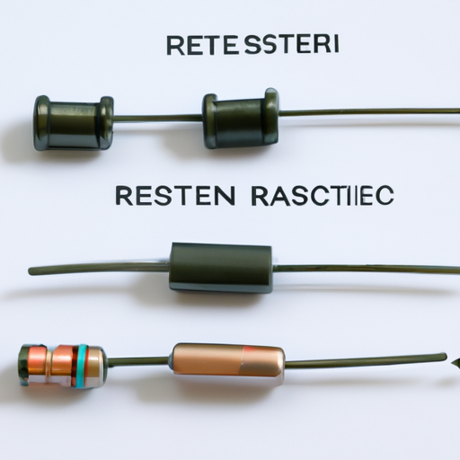
What is the mainstream resistor diagram production process?
What is the Mainstream Resistor Diagram Production Process?
I. Introduction
A. Definition of Resistors
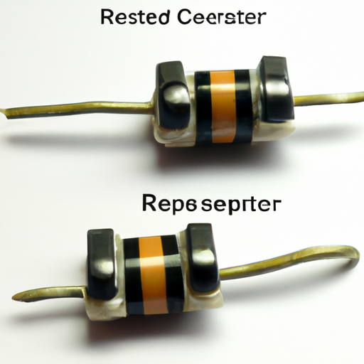
Resistors are fundamental components in electronic circuits, designed to limit the flow of electric current. They are characterized by their resistance value, measured in ohms (Ω), and play a crucial role in controlling voltage and current levels within a circuit. Resistors can be found in various forms, including fixed, variable, and specialty types, each serving specific functions in electronic applications.
B. Importance of Resistor Diagrams in Electronics
Resistor diagrams, also known as circuit diagrams or schematics, are essential for visualizing and understanding electronic circuits. They provide a graphical representation of the components and their interconnections, allowing engineers and technicians to design, analyze, and troubleshoot circuits effectively. A well-drafted resistor diagram can significantly enhance communication among team members and facilitate the manufacturing process.
C. Overview of the Production Process
The production of resistor diagrams involves several stages, from initial design to final documentation. This process requires a combination of creativity, technical knowledge, and proficiency in specialized software tools. In this blog post, we will explore the various steps involved in creating resistor diagrams, ensuring clarity and precision in electronic design.
II. Understanding Resistor Diagrams
A. Components of a Resistor Diagram
1. Symbol Representation
In resistor diagrams, components are represented by standardized symbols. For resistors, the symbol typically consists of a zigzag line or a rectangle, depending on the schematic style. Understanding these symbols is crucial for interpreting and creating effective diagrams.
2. Circuit Context
Resistor diagrams are not standalone; they exist within the context of a larger circuit. This means that the placement of resistors, their values, and their connections to other components must be carefully considered to ensure the circuit functions as intended.
B. Types of Resistor Diagrams
1. Schematic Diagrams
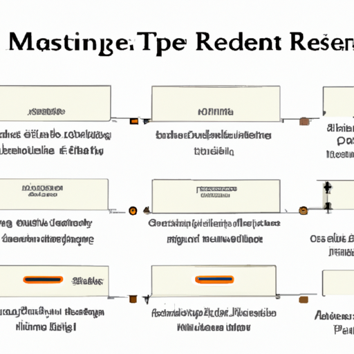
Schematic diagrams are simplified representations of electrical circuits, focusing on the functional relationships between components. They use standardized symbols and lines to depict connections, making it easier to understand the circuit's operation without getting bogged down by physical layout details.
2. Layout Diagrams
Layout diagrams, on the other hand, provide a more detailed view of how components are physically arranged on a circuit board. These diagrams are crucial for manufacturing and assembly, as they guide the placement of components and the routing of connections.
C. Applications of Resistor Diagrams in Circuit Design
Resistor diagrams are used in various applications, including consumer electronics, automotive systems, and industrial machinery. They are essential for designing new products, troubleshooting existing circuits, and ensuring compliance with industry standards.
III. The Production Process of Resistor Diagrams
A. Initial Design Phase
1. Conceptualization of the Circuit
The production process begins with the conceptualization of the circuit. Engineers and designers brainstorm ideas, considering the circuit's purpose and the specific functions of each component. This phase often involves sketching rough diagrams to visualize the overall design.
2. Selection of Resistor Types and Values
Once the circuit concept is established, the next step is to select the appropriate resistor types and values. This decision is based on the circuit's requirements, such as voltage levels, current flow, and power dissipation. Engineers must consider factors like tolerance, temperature coefficient, and physical size when making these selections.
B. Software Tools for Diagram Creation
1. CAD Software Overview
Computer-Aided Design (CAD) software plays a pivotal role in the production of resistor diagrams. These tools allow engineers to create precise and detailed diagrams, facilitating the design process. CAD software often includes libraries of standardized symbols, making it easier to represent components accurately.
2. Popular Tools Used in the Industry
Several CAD tools are widely used in the electronics industry, including Eagle, Altium Designer, and KiCad. Each of these tools offers unique features and capabilities, catering to different design needs and preferences.
C. Drafting the Diagram
1. Placement of Components
With the software in hand, engineers begin drafting the diagram by placing components in the appropriate locations. This step requires careful consideration of the circuit's layout to ensure that components are positioned logically and efficiently.
2. Wiring and Connections
After placing the components, the next step is to establish connections between them. This involves drawing lines to represent wires and ensuring that all connections are accurate. Proper wiring is crucial for the circuit's functionality, as incorrect connections can lead to malfunctions.
3. Labeling and Notation
Once the diagram is complete, engineers must label components and add necessary notations. This includes specifying resistor values, tolerances, and any other relevant information. Clear labeling is essential for ensuring that anyone reviewing the diagram can understand its contents.
D. Review and Revision
1. Peer Review Process
Before finalizing the diagram, it undergoes a peer review process. Colleagues or team members examine the diagram for accuracy, clarity, and completeness. This collaborative approach helps identify potential errors and ensures that the diagram meets industry standards.
2. Common Errors and Corrections
During the review process, common errors may be identified, such as incorrect component values, missing connections, or unclear labeling. Engineers must address these issues promptly to ensure the diagram's integrity.
IV. Finalization and Documentation
A. Exporting the Diagram
1. File Formats and Standards
Once the diagram is finalized, it must be exported in appropriate file formats. Common formats include PDF, SVG, and DXF, each serving different purposes. Engineers must also adhere to industry standards to ensure compatibility with other tools and systems.
2. Importance of Version Control
Version control is critical in the production process, as it allows teams to track changes and maintain a history of revisions. This practice helps prevent confusion and ensures that everyone is working with the most up-to-date version of the diagram.
B. Creating Supporting Documentation
1. Bill of Materials (BOM)
A Bill of Materials (BOM) is a comprehensive list of all components used in the circuit, including resistors, capacitors, and integrated circuits. The BOM is essential for procurement and assembly, providing detailed information about each component's specifications.
2. Assembly Instructions
In addition to the BOM, engineers often create assembly instructions to guide technicians during the manufacturing process. These instructions outline the steps required to assemble the circuit, ensuring that components are placed correctly and connections are made accurately.
C. Archiving and Storage of Diagrams
Once the diagrams and supporting documentation are complete, they must be archived for future reference. Proper storage practices ensure that diagrams can be easily retrieved and reused in future projects, promoting efficiency and consistency.
V. Quality Assurance in Resistor Diagram Production
A. Importance of Quality Control
Quality assurance is a critical aspect of the resistor diagram production process. Ensuring that diagrams are accurate and reliable helps prevent costly errors during manufacturing and assembly.
B. Testing and Validation of Diagrams
Testing and validation involve simulating the circuit to verify its functionality. Engineers may use simulation software to analyze the circuit's performance, identifying any potential issues before physical production begins.
C. Feedback Mechanisms for Continuous Improvement
Establishing feedback mechanisms allows teams to learn from past projects and improve future designs. Regular reviews and discussions help identify areas for enhancement, fostering a culture of continuous improvement.
VI. Future Trends in Resistor Diagram Production
A. Advances in Software and Technology
The field of electronic design is constantly evolving, with advancements in software and technology enhancing the production process. New tools and features are being developed to streamline diagram creation and improve accuracy.
B. Integration with Simulation Tools
The integration of resistor diagram production with simulation tools is becoming increasingly common. This allows engineers to test and validate their designs in real-time, reducing the risk of errors and improving overall efficiency.
C. Impact of Automation and AI on Diagram Production
Automation and artificial intelligence (AI) are poised to revolutionize the resistor diagram production process. These technologies can assist in generating diagrams, optimizing layouts, and even identifying potential design flaws, ultimately saving time and resources.
VII. Conclusion
A. Recap of the Resistor Diagram Production Process
The production of resistor diagrams is a multifaceted process that involves careful planning, design, and documentation. From the initial conceptualization to final quality assurance, each step plays a vital role in ensuring the accuracy and reliability of electronic circuits.
B. The Role of Resistor Diagrams in Modern Electronics
Resistor diagrams are indispensable in modern electronics, serving as the foundation for circuit design and analysis. They facilitate communication among engineers and technicians, ensuring that complex circuits can be understood and built effectively.
C. Encouragement for Further Learning and Exploration
As technology continues to advance, the importance of mastering resistor diagram production will only grow. Engineers and designers are encouraged to explore new tools, techniques, and best practices to stay at the forefront of this dynamic field.
VIII. References
A. Suggested Reading Materials
1. "The Art of Electronics" by Paul Horowitz and Winfield Hill
2. "Electronic Principles" by Albert Malvino and David Bates
B. Online Resources and Tools
1. [KiCad EDA](https://www.kicad.org/)
2. [Altium Designer](https://www.altium.com/)
C. Industry Standards and Guidelines
1. IPC-2221: Generic Standard on Printed Board Design
2. IEEE 315: Graphic Symbols for Electrical and Electronics Diagrams
---
This blog post provides a comprehensive overview of the mainstream resistor diagram production process, highlighting its significance in the field of electronics and encouraging further exploration of this essential topic.

