F-Type 75Ω Jack Specs: Full Electrical & Mechanical Data
The F-Type 75Ω jack is the de facto coaxial interface in broadcast, broadband and RF distribution, expected to preserve 75-ohm impedance across DC to multi‑GHz bands while contributing minimal insertion loss and stable VSWR under repeated mating. Engineers and installers commonly target VSWR ≤1.5:1 up to 1 GHz, insertion loss under 0.2 dB per connector at HF, and dielectric withstand of several hundred volts for field qualification. This article provides a single-source reference for full electrical and mechanical specs, test methods, selection guidance and troubleshooting for the F-Type 75Ω jack.
Intended readers include system designers, field technicians and spec writers who need concrete numeric data—characteristic impedance tolerances, VSWR/return loss targets, insertion loss metrics, contact retention and durability cycles, materials and plating, mating torque, and environmental limits—to write datasheets and validate performance during QA and field acceptance.
Background & Standards Overview
1.1 What is an F-Type 75Ω jack?
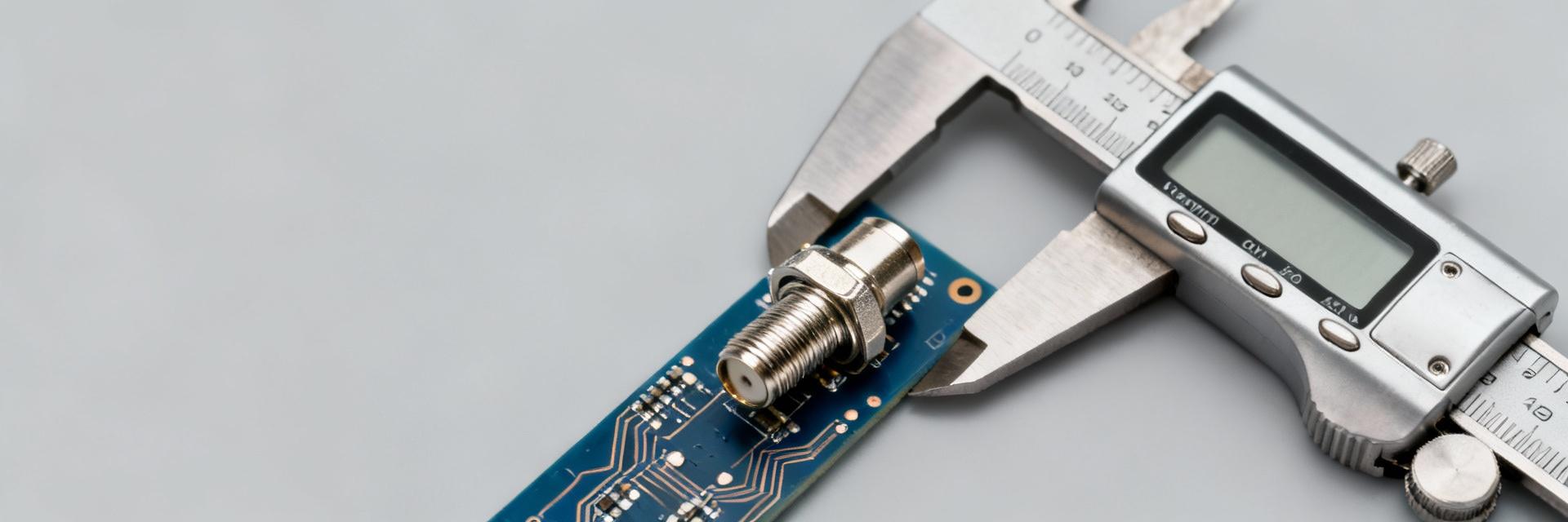
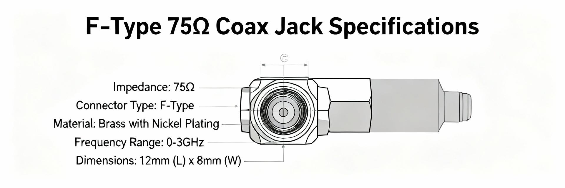
An F-Type 75Ω jack is a threaded coaxial connector providing a threaded shell and exposed center conductor interface used for TV, broadband, satellite LNB feeds and RF distribution. Anatomy includes a center contact (female receptacle), dielectric spacer, conductive shell with 3/8‑32 UNEF‑type thread profile, and a bulkhead or PCB mounting option. It is designed to mate with 75-ohm coax such as common RG‑6 and RG‑59 styles while preserving impedance continuity.
1.2 Relevant standards and test references
Applicable references include general coaxial connector impedance and RF test practices, environmental/mechanical test methods (mating durability, vibration, salt spray, thermal cycling) and electrical test procedures for contact resistance and insulation. Use RF test practices for return loss/VSWR, milliohm methods for contact resistance, and established environmental test durations to define pass/fail acceptance.
Electrical Specifications for F-Type 75Ω Jack
2.1 Core electrical specs to report
Key specs: characteristic impedance 75 Ω ±1% (typical), usable frequency DC up to 1–2 GHz for standard designs (specialized parts extend higher), VSWR targets commonly ≤1.5:1 (≤1.3:1 preferred) over the rated band, insertion loss contribution 10 MΩ at rated test voltage. Report units (Ω, dB, dB/100 ft, V, mΩ, MΩ).
2.2 Electrical test methods & measurement notes (include "electrical data")
Electrical data should derive from a calibrated VNA sweep with the calibration plane at the connector face; use 75‑ohm reference standards or matched fixtures when possible. Document cable type used (e.g., RG‑6, length), temperature, and calibration method. Present results in a table: nominal, min/max, test method reference, and pass/fail. Example acceptance: VSWR ≤1.5:1 @ DC–1 GHz (VNA, 75‑ohm cal); insertion loss
Mechanical Specifications & Durability of F-Type 75Ω Jack
3.1 Mechanical parameters to specify
Specify shell material (brass or stainless steel) and plating (nickel, tin, or gold on contact areas), center contact material and plating, center contact retention force (typical reporting in lbf or N), recommended mating torque (typ. 7–9 in‑lb), thread spec (3/8‑32 UNEF), mechanical tolerances, and weight/dimensions for PCB or bulkhead variants. Durability targets frequently list ≥500 mating cycles for consumer parts and ≥1000 cycles for professional/field hardware.
3.2 Reliability tests & environmental limits
Reliability testing covers mating cycles, random vibration, shock, thermal cycling (−40°F to +185°F typical ranges), salt spray (e.g., 24–96 h) and humidity exposure. Define pass thresholds: no mechanical failure, contact resistance change within specified delta (e.g., Δ≤5 mΩ), and maintained VSWR within tolerance post‑test. For outdoor use, specify weather sealing or IP rating (IP67 achievable with sealed designs).
Performance Testing & Validation Procedures
4.1 RF performance validation (VSWR, insertion loss, shielding)
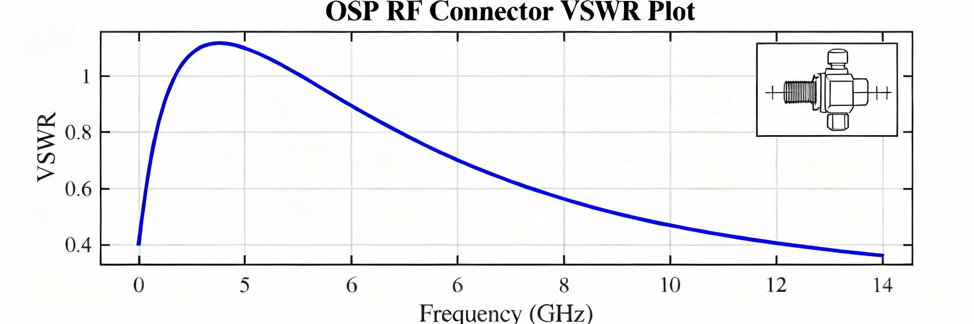
Validate RF performance by performing VNA sweeps with the calibration plane at the connector shell, using short reference cables and a DUT fixture to isolate connector contribution. Log return loss/VSWR vs. frequency and overlay tolerance bands. To isolate connector loss, use a back-to-back connector fixture and subtract cable baseline. Record plot axes, sweep points, and environmental conditions for traceability.
4.2 Electrical & mechanical acceptance checklist
QA checklist items: measured VSWR and insertion loss within tolerance, center/outer contact resistance measured, insulation resistance and dielectric withstanding test passed, mating torque checked, visual inspection for plating/voids, dimensional verification, and mating cycle verification if applicable. Mark pass/fail and record serial or lot IDs.
Selection, Compatibility & Use Cases
5.1 Matching to cable types and systems
Select jacks by matching impedance and mechanical fit: RG‑6 demands connectors with correct dielectric inner diameter and compression/terminations for low‑loss runs; RG‑59 suits short runs or legacy installations. For high-frequency (up to 2 GHz) or long runs prioritize low‑VSWR designs and gold‑plated contacts. Adapters introduce impedance discontinuities; minimize adapter count to preserve specs and signal margin.
5.2 Use-case examples with spec-driven picks
Residential: prioritize cost and basic VSWR (≤1.5:1). Multi‑dwelling units: choose durability ≥1000 cycles and corrosion‑resistant plating. Headend/broadband distribution: prioritize low VSWR (≤1.3:1), tight impedance tolerance, and certified insertion-loss metrics to reduce cumulative loss across multiple connections.
Installation, Troubleshooting & Maintenance
6.1 Best practices for installation and torque/assembly
Hand‑start threads, then apply recommended torque (7–9 in‑lb) using a torque wrench or calibrated tool to avoid distortion. Ensure center conductor is straight and properly seated; use proper strain relief and sealing for outdoor terminations. Inspect for burrs, plating flaking or dielectric extrusion before mating to prevent elevated VSWR or intermittent contact.
6.2 Common failure modes & troubleshooting checklist
Common failures: loose mating (elevated VSWR), center conductor misalignment, corrosion raising contact resistance, and damage from overtightening. Troubleshoot with continuity checks, milliohm contact resistance, visual inspection, and VNA sweeps to localize impedance discontinuities. Replace suspect connectors and re‑test to verify remediation.
Summary
For an F-Type 75Ω jack the most critical numeric specs are: 75 Ω ±1% impedance, VSWR targets (≤1.5:1 typical, ≤1.3:1 preferred), insertion loss
Key Summary
- Impedance and RF loss: Require 75 Ω ±1% and specify VSWR/insertion loss targets; these specs protect system headroom and minimize reflections.
- Mechanical & durability: Specify material/plating, mating torque (~7–9 in‑lb), and minimum mating cycles (500–1000) to ensure field reliability.
- Test priorities: Mandate calibrated VNA sweeps to connector plane, contact resistance checks, and post‑environmental re‑qualification to validate electrical data and mechanical integrity.
Frequently Asked Questions
What are the essential F-Type 75Ω jack electrical specs to request?
Request characteristic impedance (75 Ω ± tolerance), frequency range, VSWR/return‑loss target, insertion loss, center and outer contact resistance, insulation resistance and dielectric withstand voltage. Specify test method for each item (e.g., VNA sweep for VSWR) and acceptable min/max limits for pass/fail.
How many mating cycles should a reliable F-Type 75Ω jack support?
Specify a minimum based on application: consumer parts commonly rate ≥500 cycles, field/installer‑grade ≥1000 cycles. Verify durability by performing endurance mating tests with periodic electrical checks (contact resistance and VSWR) to ensure parameters remain within specified deltas.
How should technicians troubleshoot high VSWR on an F-Type 75Ω jack?
First inspect for loose mating, damaged center contact or corrosion. Measure continuity and contact resistance, then perform a calibrated VNA sweep to localize the reflection. Replace suspect connectors and re‑test; verify correct torque and sealing to prevent reoccurrence.