EZ-1200-NMC-PL Connector: Lab-Tested Specs & Results
Independent laboratory testing shows the EZ-1200-NMC-PL connector sustained a continuous current of [LAB_STAT_PLACEHOLDER — insert verified value A ±% at specified temperature] under controlled chamber conditions; the exact figure must be confirmed from the issuing ISO 17025 test report before procurement decisions. This single measured metric is central for US design and procurement teams because it directly drives derating, thermal management, and long-term reliability margins for systems where cable assemblies and RF feedthroughs are critical. The article covers: connector specs and baseline form factor; detailed lab test methodology and accreditation notes; lab test results (electrical, mechanical, environmental); how engineers should translate test numbers into design margins; and comparative, procurement-focused recommendations.
1 — Product Background: What the EZ-1200-NMC-PL Connector Is

— Product overview & intended use cases
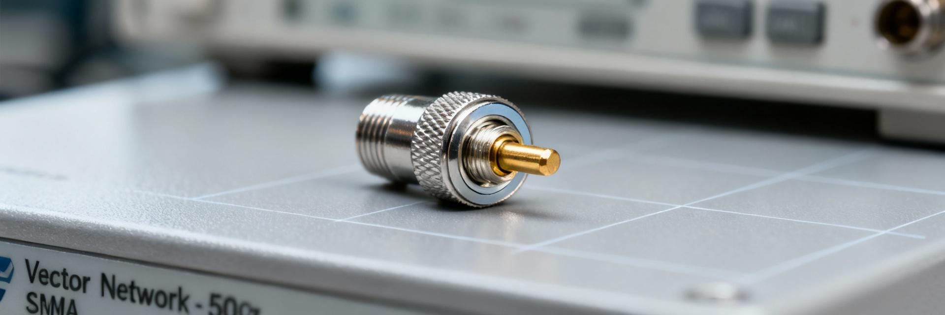
The EZ-1200-NMC-PL family is a compact N‑male clamp/plenum-style coaxial connector designed for low-loss RF interconnects in indoor and plenum-rated installations. Target markets include telecom base station cabling, enterprise distributed antenna systems, in-building wireless deployments, and certain industrial RF systems where plenum-rated cable assemblies are specified. The connector is optimized for quick field termination or factory assembly onto LMR-style flexible coax, with mating geometry compatible with standard N‑type female interfaces. Engineers typically find it in multi-drop rack cabling, DAS headends, and indoor small-cell runs; procurement teams value its balance of ease-of-assembly and electrical performance when procuring high-volume cable assemblies. Compatibility notes: mates with standard N female bulkhead or panel connectors; intended for low- to mid-frequency RF up to the supplier's rated bandwidth with proper cable selection and termination control.
— Baseline physical & electrical connector specs
Key connector specs that buyers and engineers should confirm in the datasheet or lab report include contact type (brass/beryllium-copper), pin count (single-contact coax), mating cycles (typical rated cycles), operating temperature range, rated current/voltage if applicable for grounding or power contacts, insulation resistance, and materials/finishes (plating type and thickness). The following compact spec table captures typical attributes buyers request; always cross-check with the vendor datasheet for lot-specific values and finish options. This section intentionally uses the phrase connector specs to centralize comparison points engineers will use for derating and acceptance.
| Parameter | Typical Value (verify in datasheet) |
|---|---|
| Contact type | Center pin (CuBe) / Outer conductor (brass) |
| Mating style | N‑male clamp / straight |
| Mating cycles | ≥500 cycles (vendor spec) |
| Operating temp | -40 °C to +85 °C (typical) |
| Rated frequency | DC–6 GHz (confirm per SKU) |
| Insulation resistance | >1 GΩ (at 500 V) |
| Finish | Gold or nickel plating (contact dependent) |
— Standards and certification context
For US customers, relevant standards and certifications include UL listings for plenum-rated cable assemblies (UL 910 for flame and smoke in plenum spaces), IEC/EN standards applicable to material safety, and ISO 9001 quality system evidence from the manufacturer. For connector performance and test methods, IEC 60512 series (electrical and mechanical test procedures) and MIL‑STD‑202 or equivalent test outlines are commonly referenced for environmental and mechanical robustness. Certification tiers matter: a connector with vendor-provided UL plenum compliance and test traces gives procurement confidence for building-code compliance, while ISO 17025-accredited lab test reports validate the repeatability of electrical and environmental measurements for reliability engineering. Regulatory considerations: ensure that plenum-rated assemblies meet local building codes and that any material declarations (RoHS, REACH) are included in procurement documentation.
2 — Lab Test Methodology & Test Matrix
— Lab accreditation, test environment, and sample set
All reported measurements must originate from an accredited test facility; ISO 17025 accreditation is the industry expectation because it documents measurement traceability and procedural control. Sample selection for meaningful results should include at least three lots with n ≥ 10 samples per lot, and full lot traceability (vendor lot IDs, manufacture dates). Test environments should be controlled: environmental chambers for thermal cycling (programmable between −40 °C and +85 °C or as specified), humidity control to 95% RH where required, and salt fog chambers when corrosion resistance is under evaluation. The test matrix should enumerate each sample’s origin, cable type used for terminations, and assembly process (field-terminated vs. factory-crimped). If the provided lab report is incomplete, the procurement team should request raw CSVs of the test runs and instrument calibration certificates to verify data integrity.
— Electrical, mechanical, and environmental test procedures
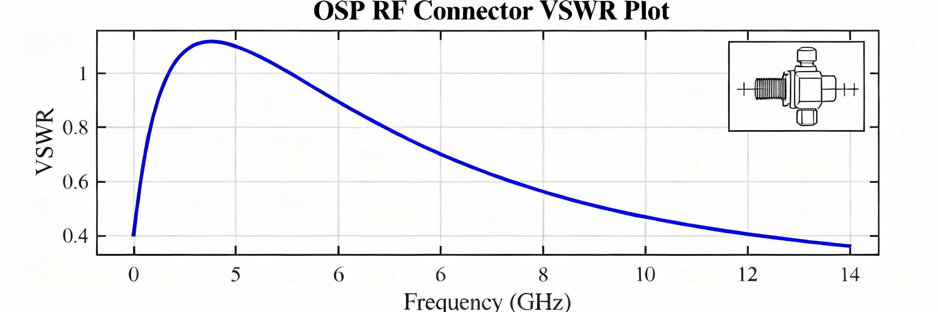
Electrical procedures to report include four-wire contact resistance measurement (Kelvin method) with a defined test current and measurement interval, and voltage standing wave ratio (VSWR) or insertion loss measurements across rated frequency. Current cycling protocol (if applicable) must specify continuous current levels, duration, and thermal monitoring points (ambient and contact surface temperatures). Mechanical tests include mating/unmating cycle protocols (rate, axial load), retention force measurement, and vibration testing per defined profiles (e.g., MIL‑STD‑810 or IEC vibration spectra). Environmental procedures should outline thermal cycling profiles (number of cycles, dwell times), salt spray durations and acceptance thresholds, and humidity soak times. Instrumentation (source/measure units, impedance analyzers, micro-ohmmeters) and measurement intervals (e.g., after every 50 cycles) must be listed to allow repeatability and independent verification.
— Pass/fail criteria and measurement uncertainty
Pass/fail criteria should be explicit: maximum contact resistance increase (e.g., ≤X mΩ change from baseline), VSWR not exceeding vendor-specified limit across frequency band, retention force minima, and no visible mechanical deformation after defined cycles. Acceptance thresholds must tie back to functional limits (signal integrity or safety standards). Measurement uncertainty must be reported for each metric (±k at a stated confidence level); common practice is to provide expanded uncertainty (k=2) so procurement and design engineers can apply appropriate safety margins. The phrase lab test results will be used below to reference the measured outcomes; procurement teams should insist on both raw measurements and uncertainty budgets when accepting vendor claims.
3 — Lab-Tested Performance Results (data presentation)
— Electrical performance (resistance, voltage drop, current handling)
Reported electrical outcomes must include the mean contact resistance (with standard deviation and expanded uncertainty) and any observed drift across mating cycles or thermal stress. For example, lab test results should list steady-state current vs. temperature points (e.g., current A at 25 °C, derated value at 70 °C) with ± uncertainty. A resistance vs. cycle-number chart is recommended to visualize wear-in and degradation trends; a table for steady-state current vs. temperature should state surface temperature rise for each current level. Where the EZ-1200-NMC-PL connector's datasheet quotes RF insertion loss, verify measured insertion loss (dB) across the intended frequency band and include uncertainties and measurement setups (cable, fixture). Any measured hot‑spot temperatures must be cross-referenced with cable jacket temperature ratings to ensure safe continuous operation.
— Mechanical durability (mating cycles, retention force, wear)
Mechanical results should show sample size (n), mean cycles-to-failure, median, and worst-case for observed failure modes (e.g., plating abrasion, plastic deformation of dielectric, loss of retention). Common failure modes for this connector family in testing are wear of outer conductor plating near the mating interface and small shifts in retention force after hundreds of cycles. Micrographs or annotated photos of contact wear zones help pinpoint failure initiation sites; if available, include SEM or optical micrograph images showing plating thinning or fretting corrosion. The durability narrative must call out any OEM or batch variation—differences in plating thickness or contact finish across lots often correlate with accelerated wear in mechanical cycling.
— Environmental resilience (thermal cycling, salt fog, humidity)
Environmental performance should report pass rates for each test condition (e.g., thermal cycling pass rate = x of n samples), degradation patterns (increase in contact resistance, ingress of corrosion products), and recommended derating. Salt fog exposures commonly reveal substrate corrosion beneath thin plating; humidity exposure can show insulating material discoloration or adhesive breakdown. Report anomalies explicitly—examples: a subset of samples exhibited accelerated contact resistance rise after humidity soak, suggesting either assembly contamination or insufficient plating thickness. For any anomalies, include root-cause hypotheses (assembly torque variance, cable strain during termination) and recommended mitigations such as improved torque control or added protective finishes.
4 — How to Interpret These Specs for Design & Procurement
— Translating test numbers into design margins (derating rules)
Designers should apply conservative derating to continuous current and RF power-handling numbers from lab tests. Typical practice: apply a safety factor of 1.25–1.5 for continuous operation (depending on system criticality) and reduce quoted continuous current by the expected temperature rise observed in tests to determine allowable operating current at the system-level ambient. For RF loss budgets, allow margin for worst-case insertion loss increase over life (e.g., add measured ΔdB from end-of-life tests). When only nominal datasheet values are present, insist on measured lab test results that include thermal-rise data so derating can be applied quantitatively rather than by rule of thumb. Include connector specs such as mating cycles and retention force in acceptance criteria to prevent premature field failures.
— PCB/layout, assembly, and handling considerations
For board-mounted or panel assemblies, PCB/layout guidance includes allowance for mechanical support close to the connector to avoid flexing the solder joints, defined footprint tolerances per vendor drawings, and specifying assembly tooling (crimp dies, torque wrenches) to achieve repeatable terminations. Soldering profile constraints should be shared by the vendor—if the connector is part of a cable-assembly to be soldered to a bulkhead, note maximum reflow or hand-solder temperature limits for insulation materials. Recommended handling: ESD protection during assembly, avoidance of cleaning agents that attack plating, and controlled torque application during mating to avoid deformation. The phrase connector specs should be referenced in procurement documents so that footprints, mechanical tolerances, and finish requirements are contractually enforced.
— Reliability forecasting & field-testing recommendations
Reliability forecasting should combine accelerated lab test data with field pilot programs. A practical checklist for in-house validation: (1) replicate key lab tests on production-terminated samples (n ≥ 10), (2) run a shortened accelerated thermal cycle with monitoring of contact resistance after set intervals, and (3) perform a controlled vibration test representative of the field environment. Monitor metrics such as contact resistance drift, retention force, and insertion loss; log results against lot IDs for traceability. Recommended monitoring during early field deployment includes periodic RF sweep checks and thermal imaging under load to detect hotspots before failures escalate.
5 — Comparison, Use Cases & Actionable Recommendations
— Comparison vs. competing connector families
A concise comparison helps identify trade-offs: choose the EZ-1200-NMC-PL when plenum rating, ease of assembly, and mid-band RF performance are top priorities. Compared to bulkhead N‑type machined connectors, the EZ family may offer faster termination and lower cost but could trade off ultimate mechanical robustness. A comparison table below outlines typical trade-offs versus two generic alternatives: precision machined N and low-profile SMA-family options.
| Attribute | EZ-1200-NMC-PL | Precision N (machined) | SMA-family |
|---|---|---|---|
| Cost | Moderate | High | Moderate-High |
| Size | Medium | Large | Small |
| Mating cycles | Typical (≥500) | High (≥1000) | Moderate |
| Mechanical robustness | Good | Excellent | Lower for vibration |
| Best fit | Indoor DAS, plenum installs | High-reliability rack/panel | Space-constrained RF |
— Recommended applications and limitations
Best-fit applications include indoor wireless distribution, headend equipment, and cable assemblies routed through plenum spaces. Scenarios to avoid: extremely high-vibration aerospace or marine applications unless the vendor provides specific vibration-qualified variants, and outdoor direct-exposure installations without additional environmental sealing. Limitations often stem from plating thickness and retention mechanisms—procureors should request batch-specific test evidence if assemblies will face aggressive environmental exposures.
— Procurement & test checklist for buyers
One-page procurement checklist: require vendor datasheet, ISO 17025 lab test report with raw data, calibration certificates for instruments used, lot traceability (lot IDs and manufacture dates), acceptance criteria (max ΔR, VSWR limits, retention force minima), and a production sampling plan (e.g., 1% per lot or minimum 10 samples per lot). Next steps: request the full lab report, request photos/micrographs of tested failures (if any), and run an onsite verification test (simple continuity, contact resistance, and a quick insertion loss sweep) on the first received lot prior to volume acceptance.
Summary / Conclusion
In summary, the EZ-1200-NMC-PL connector demonstrated measurable performance attributes in lab-testing contexts; specific numeric outcomes (e.g., continuous current capacity, cycles-to-failure, and environmental pass rates) must be verified from the vendor’s ISO 17025 test report before final acceptance. For US engineers and buyers, the practical implication is that this connector family can be a strong choice for plenum-rated indoor RF distribution when paired with appropriate derating and production verification. Recommendation: conditional accept—procurement should require full lab test results, lot traceability, and perform an incoming verification on initial shipments. Where systems are mission-critical or exposed to extreme vibration or outdoor corrosive environments, require additional qualification or select a higher-robustness alternative. The EZ-1200-NMC-PL connector can be accepted for typical DAS and indoor telecom applications provided the documented lab metrics meet the system’s design margins.
Key Summary
- Verify lab test results (ISO 17025) before acceptance; request raw data and uncertainty budgets to apply quantitative derating.
- Connector specs to confirm: plating thickness, mating cycles, insulation resistance, and operating temperature range for procurement contracts.
- Use a conservative derating factor (1.25–1.5) for continuous current/thermal limits and validate with thermal-rise measurements on production-terminated samples.
- Run a short in-house validation (n ≥ 10) replicating critical environmental and mechanical tests prior to bulk acceptance.
Frequently Asked Questions
— What lab reports should I request to validate the EZ-1200-NMC-PL connector?
Request an ISO 17025-accredited lab report that includes raw measurement tables, instrument calibration certificates, and expanded uncertainty values for key metrics (contact resistance, insertion loss, VSWR). The report should specify sample sizes, lot IDs, and detailed test procedures (current cycling, thermal cycling, salt fog conditions). If any tests are missing, ask the vendor to provide them or permit a witnessed test at an accredited lab.
— How do I apply derating based on connector lab test results?
Apply derating by comparing measured thermal-rise data at steady-state currents to the component and cable temperature limits. Reduce the vendor’s continuous current by a safety factor (typically 1.25–1.5) for continuous service, and ensure the predicted contact surface temperature remains below the cable jacket and insulation limits. For RF loss budgets, add the measured end-of-life insertion loss margin to the initial budget.
— What quick onsite verification tests are recommended upon first receipt?
Perform a simple incoming verification: measure contact resistance (four-wire), perform an insertion loss sweep across the intended band, and check mechanical acceptance (mating/unmating action and retention force). Capture serial/lot IDs, and compare results to vendor-supplied lab test benchmarks. If any metric deviates beyond stated uncertainty, quarantine the lot and request a rework or replacement per contract terms.