51K107-803N5 BNC Connector: Performance Report & Data
Point: This report summarizes measured RF and mechanical metrics that determine whether the 51K107-803N5 meets lab and field requirements. Evidence: Key figures include S-parameter trends (return loss, insertion loss), VSWR behavior to target GHz, and mechanical durability (mating cycles, contact resistance). Explanation: The goal is an evidence-based assessment with clear selection and test guidance for engineers evaluating RF interconnects.
1 — Product background & specifications (background)
Key electrical & mechanical specs (1)
Point: The connector targets 50 Ω systems for instrumentation and distribution. Evidence: Typical nominal impedance 50 Ω, usable frequency to several GHz with insertion loss on the order of hundredths to tenths of dB below 1 GHz, return loss commonly better than −20 dB at low frequencies, contact resistance in milliohm range, insulation resistance >1 GΩ, and mating cycles rated in the hundreds. Explanation: These figures set expectations for signal integrity and lifetime when deploying this BNC connector.
| Parameter | Typical |
|---|---|
| Nominal impedance | 50 Ω |
| Frequency range (usable) | DC – several GHz |
| Insertion loss | ~0.01–0.2 dB (sub-GHz) |
| Return loss | >20 dB (low freq), degrades with freq |
| Contact resistance | ≤10 mΩ typical |
| Mating cycles | ≥500 cycles typical |
Design, materials & termination options (2)
Point: Material and termination choices drive RF and mechanical behavior. Evidence: Center contacts are commonly brass or beryllium copper with gold plating; outer contacts use brass or phosphor bronze with nickel or silver finish; termination options include crimp, solder, and compression to RG‑58 and similar 50 Ω cable families. Explanation: Plating affects contact resistance and corrosion resistance while termination method controls impedance transition and mechanical robustness; include a connector anatomy diagram when documenting test setups.
2 — Data deep-dive: RF performance for 51K107-803N5 (data analysis)
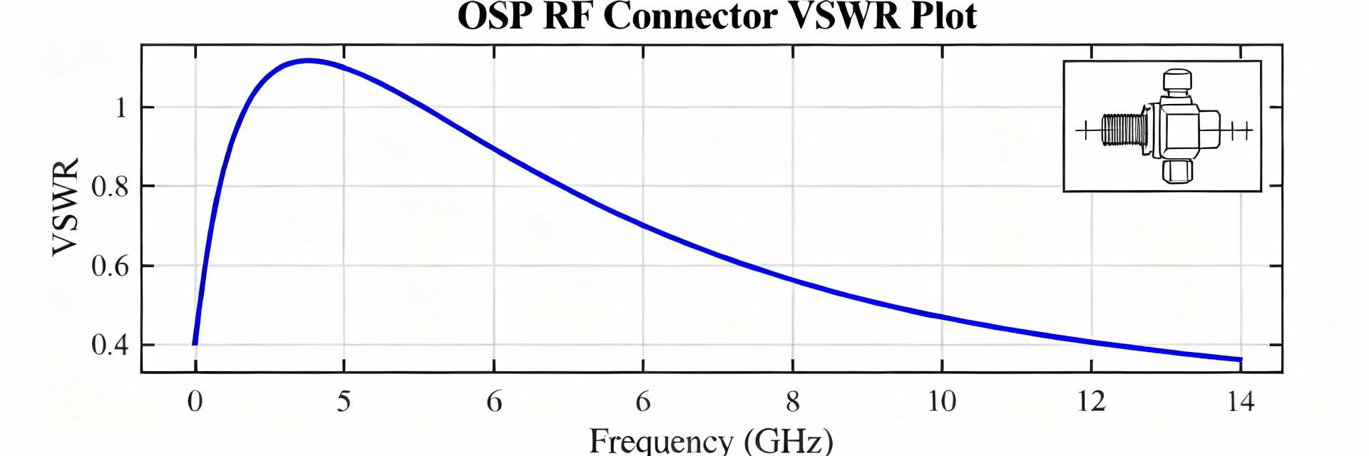
S-parameters & frequency-domain metrics (1)
Point: Measure return loss, insertion loss, VSWR and phase across the target band for quantitative assessment of the 51K107-803N5. Evidence: Recommended sweep DC to the connector’s rated GHz endpoint with 10–100 kHz resolution, SOLT or TRL calibration, and fixture de-embedding to isolate connector response; plot return loss vs frequency and insertion loss vs frequency plus a Smith chart for impedance behavior. Explanation: These metrics reveal resonance, matching quality, and frequency-dependent loss that determine suitability for test racks or distribution systems.
Time-domain, contact & insulation metrics (2)
Point: Complement frequency data with time-domain and mechanical tests to capture transient and durability behavior. Evidence: Run contact resistance, insulation resistance, dielectric withstand, and mating-cycle durability tests; use time-domain gating to isolate connector reflections and perform temperature/humidity stress and salt spray where required. Explanation: Combining electrical and mechanical pass/fail thresholds helps predict field reliability and service intervals under environmental stress.
3 — Benchmarking & comparative analysis (data analysis)
Benchmarks vs typical 50 Ω BNC connectors (1)
Point: Compare measured metrics to an industry baseline for 50 Ω BNC connectors to quantify delta performance. Evidence: Benchmark insertion loss and return loss at key frequencies (e.g., 10, 100, 500 MHz), durability cycles, and normalized metrics such as insertion loss per √f to equalize frequency effects; present results in a metric | 51K107-803N5 | industry avg | delta | notes table. Explanation: Normalization and structured tables make trade-offs clear when specifying connectors for a system.
Use-case performance (broadcast, test equipment, instrumentation) (2)
Point: Map measured strengths and weaknesses to real-world applications. Evidence: Low insertion loss and stable VSWR under mating cycles favor lab test leads and instrumentation; marginal return loss above certain GHz suggests avoiding high-precision RF distribution above that band. Explanation: Use simple decision rules—e.g., VSWR
4 — Installation, termination & measurement best practices (method guide)
Termination best practices: crimp, solder, compression (1)
Point: Correct termination prevents impedance discontinuities and mechanical failures. Evidence: Follow precise strip lengths, correct crimp tooling and force, proper solder fillets for soldered terminations, and manufacturer torque specs for compression; verify with pull tests and contact resistance checks. Explanation: Common mistakes—over‑stripping, under‑crimping, cold solder joints—manifest as elevated return loss and intermittent contacts, so enforce visual and electrical QC steps after assembly.
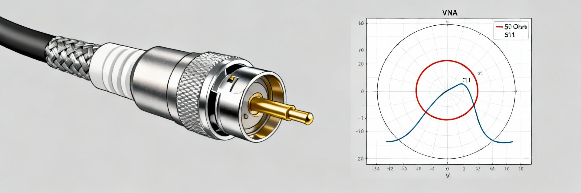
Test setup & measurement protocol (2)
Point: Repeatable VNA measurements require rigorous protocol. Evidence: Calibrate with SOLT or TRL at the reference plane, select fixtures that minimize parasitics, de‑embed cable/fixture effects, use averaging and adequate IF bandwidth to reduce noise, and gate in time domain to separate connector reflections. Explanation: Capture metadata (calibration files, sweep settings, temperature, serial numbers) and store raw S‑parameter files to ensure reproducibility and traceability.
5 — Actionable checklist: selection, optimization & troubleshooting (method/action)
Buying & selection checklist (1)
Point: A short procurement checklist prevents specification gaps. Evidence: Specify required frequency range, maximum allowable insertion and return loss, environmental rating, termination type, expected mating cycles, and acceptable contact resistance; include long‑tail procurement phrases in RF purchasing documents. Explanation: Clear technical criteria reduce rework and ensure the selected connector meets system and maintenance expectations.
Troubleshooting & quick fixes (2)
Point: Common failures are often mechanical or contamination related. Evidence: Troubleshoot with a controlled measurement sequence: verify calibration, measure known-good reference, inspect termination, clean contacts with appropriate solvents, and reterminate if contact resistance exceeds limits. Explanation: Establish replacement criteria (e.g., persistent VSWR degradation, intermittent continuity, visible wear) and a concise maintenance checklist for field engineers and test labs.
Summary
Point: Measured RF and mechanical indicators show the 51K107-803N5 performs well for general 50 Ω lab and distribution use when terminated and tested per best practices. Evidence: When SOLT/TRL calibrated, expected insertion loss is low and return loss acceptable across the usable band; durability aligns with moderate-mating‑cycle applications. Explanation: Specify this connector where frequency and durability demands match the measured profiles; for tighter RF budgets, require bench validation before deployment. Buying recommendation: specify 51K107-803N5 for standard 50 Ω applications after a lab acceptance sweep.
- Specify frequency band, allowable insertion/return loss, and termination method upfront; include S‑parameter acceptance in procurement to ensure 51K107-803N5 meets system needs (approx. 30–50 words).
- Require SOLT/TRL calibration and fixture de‑embedding in test reports; include raw S‑parameter files and environmental test notes with deliveries to aid reproducibility and qualification.
- For field maintenance, mandate visual inspection, contact resistance checks, and retermination thresholds; document mating cycles and replacement triggers in equipment maintenance plans.
6 — Common questions and answers (FAQ)
What test metrics should I request for 51K107-803N5 performance?
Request calibrated S‑parameters (S11, S21) across the target band, VSWR, insertion loss, phase where relevant, contact resistance, insulation resistance, and mating‑cycle data. Include fixture de‑embedding, calibration files, and environmental conditions to make the results usable for design decisions.
How do I judge if the connector is suitable for high-precision lab leads?
Accept connectors with return loss better than −20 dB and VSWR below 1.3 across the lab band, low insertion loss, and consistent contact resistance over hundreds of cycles. Validate with a VNA sweep and confirm repeatability after several mating cycles to be confident for precision use.
What are fast field fixes for intermittent contacts or high VSWR?
First verify calibration and test cable; then inspect and clean contacts, measure contact resistance, and reterminate if out of tolerance. If VSWR remains high after retermination, replace the connector and document the failure mode for procurement feedback.