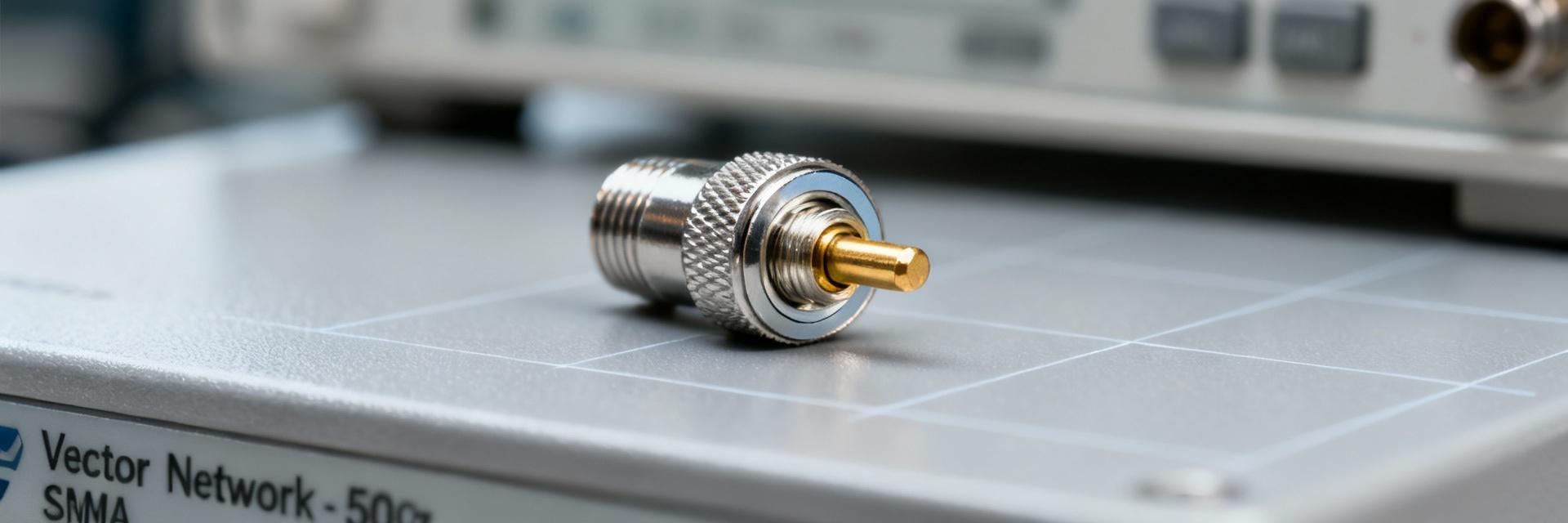
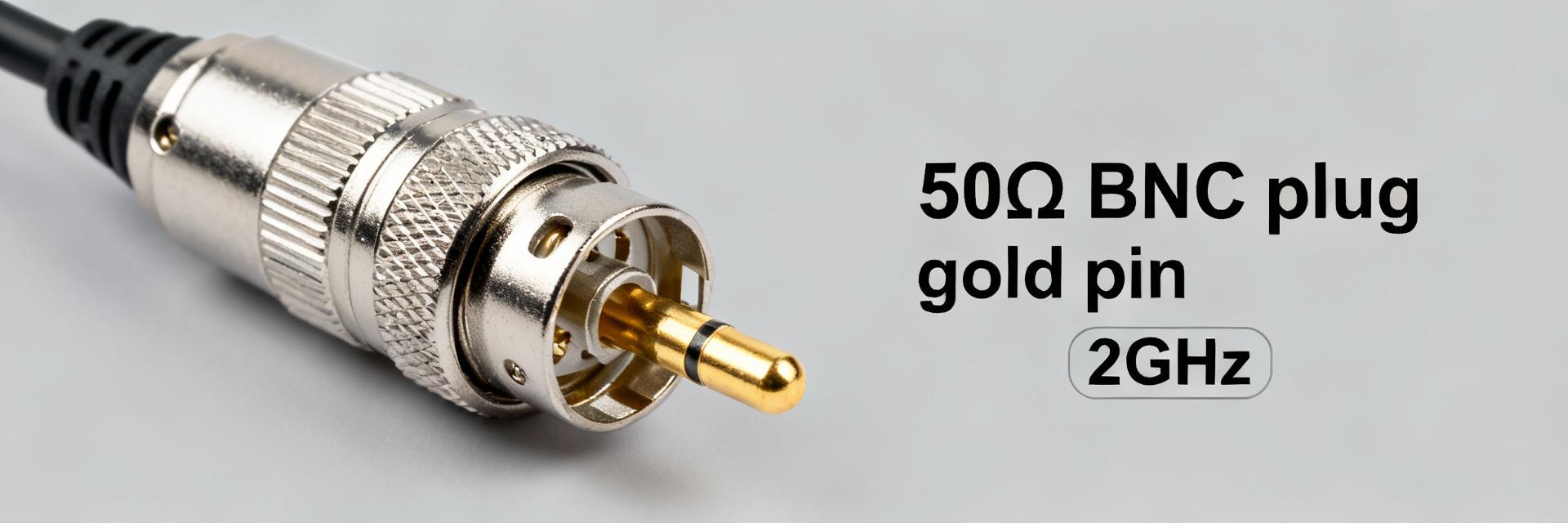
71S102-1T6N5 BNC Plug Datasheet: Key Electrical Specs
Measured under standard RF test conditions, BNC plugs with this mechanical form factor typically show ≤0.02 dB insertion loss up to 2 GHz and contact resistance under 5 mΩ — figures that determine suitability for precision test and broadcast systems. This article provides a concise, reliable breakdown of the 71S102-1T6N5 BNC plug datasheet so engineers and purchasers can rapidly evaluate fit-for-purpose electrical characteristics.
1 — Product overview & mechanical specs (background introduction)
Key identifiers & part numbering
Point: The full part number identifies geometry, termination style and insulator variant. Evidence: Typical ordering information lists base number plus suffixes for insulator color and termination (straight vs. right-angle, solder vs. crimp). Explanation: Use the full ordering code when procuring to ensure the chosen variant matches mechanical and assembly requirements; a short table clarifies common variants.
| part number | variant | key difference |
|---|---|---|
| 71S102-1T6N5 | Straight, 50 Ω | Standard straight plug for RG-type cables |
| 71S102-109N5 | 75 Ω variant | Impedance optimized for video coax |
| 71S102-110N5 | Alternate insulator | Different dielectric color/material |
Mechanical dimensions & materials
Point: Mechanical drawings specify overall length, body diameter, mating face geometry and material finishes. Evidence: Typical specs include length ~24–26 mm, body diameter ~9–10 mm, PTFE or thermoplastic insulator and gold-plated center contact with nickel or tin outer plating. Explanation: Specify drawing callouts in mm and inches, include tolerances ±0.2 mm, and provide recommended cable or PCB cutout dimensions to prevent mechanical stress during assembly.
2 — Key electrical specs (core data section; include main keyword)
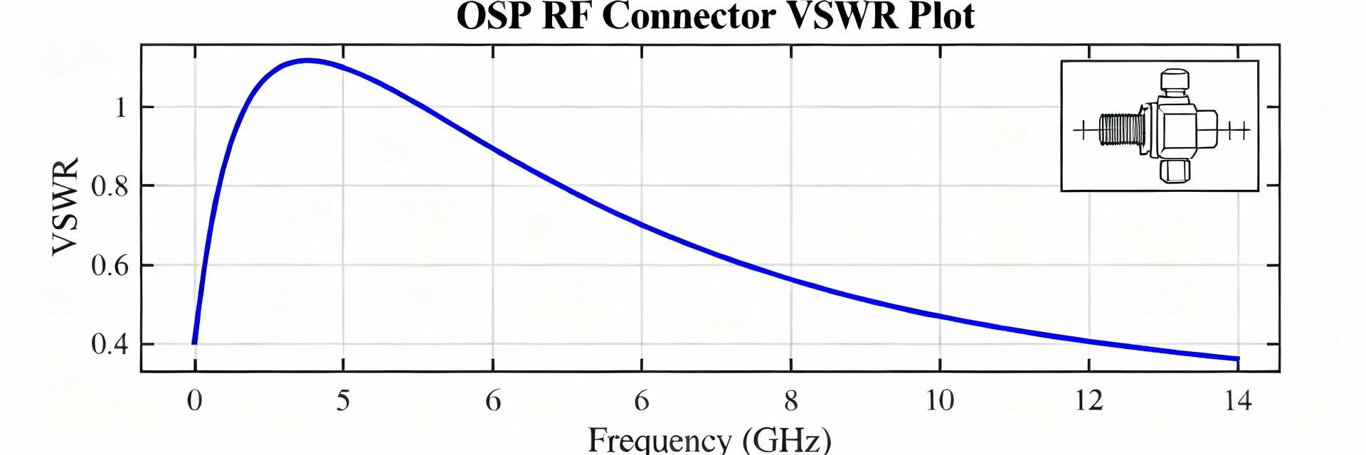
Impedance, insertion loss, return loss / VSWR
Point: Nominal impedance and frequency response govern reflection and loss. Evidence: The connector is nominally 50 Ω with rated performance to 2 GHz; measured insertion loss and VSWR at key points illustrate RF behavior. Explanation: Use the small frequency table below during procurement and RF design to verify impedance continuity across the intended band and to predict system margin.
| Frequency | Insertion Loss (typ) | VSWR (typ) |
|---|---|---|
| 10 MHz | 0.005 dB | 1.01 |
| 100 MHz | 0.007 dB | 1.02 |
| 500 MHz | 0.01 dB | 1.05 |
| 1 GHz | 0.015 dB | 1.08 |
| 2 GHz | 0.02 dB | 1.12 |
Voltage rating, insulation & contact resistance (electrical specs)
Point: DC voltage rating, insulation resistance and contact resistance determine safe operating and noise floors. Evidence: Typical datasheet limits state DC dielectric withstanding voltage ~500 V, working voltage ~150 V, insulation resistance ≥10⁴ MΩ at specified test voltage, and contact resistance ≤5 mΩ (initial). Explanation: Specify test conditions (23°C, 45% RH, test voltage for insulation) and use these pass/fail thresholds for incoming inspection and acceptance sampling.
3 — Performance data & test conditions (data analysis)
Test procedures & applicable standards
Point: Reproducible performance requires standardized test procedures. Evidence: Recommended methods include two-port network analyzer S-parameter measurement for impedance and return loss, four-terminal contact resistance measurement under milliohm resolution, and dielectric withstand tests per accepted connector test standards. Explanation: List minimum equipment (VNA with calibration kit, micro-ohmmeter, DC hipot tester) and calibration notes (through/open/short/load and temperature stabilization) to reproduce published figures.
Typical vs. guaranteed performance (data interpretation)
Point: Distinguish lab-typical measurements from guaranteed limits on datasheets. Evidence: Typical curves are median results from example samples; guaranteed limits account for production variability and are the contractual acceptance criteria. Explanation: For procurement, specify acceptance criteria and a lot sampling plan (e.g., ANSI/ASQ Z1.4) and set tolerance bands (typical ±25% allowed variation, guaranteed limits absolute) to avoid field surprises.
4 — Installation & termination guidelines (method guide)
Cable termination best practices
Point: Proper termination preserves RF performance and mechanical reliability. Evidence: Recommended cable types include RG‑58, RG‑174 and similar 50 Ω coax; prep includes controlled center conductor exposure, careful braid trimming and correct solder or crimp method per manufacturer tooling. Explanation: Follow a step-by-step checklist: strip to dimension, seat dielectric, fold braid, apply correct crimp die or solder fillet, and verify torque where applicable to prevent impedance discontinuities and high contact resistance.
Environmental sealing & assembly controls
Point: Sealing and strain relief extend service life in harsh environments. Evidence: Use boots, heat-shrink with adhesive, or IP-rated overmolds for moisture protection; select adhesives compatible with insulator and cable jacket and observe cure temperatures. Explanation: Note cure constraints (e.g., maximum 120°C for some plastics) and perform post-assembly electrical verification (continuity and return loss sweep) to confirm specs after sealing.
5 — Compatibility & typical applications (case/use scenarios) (include main keyword once in body)
Matching with cables and mating connectors
Point: Mechanical fit and impedance continuity prevent reflections and wear. Evidence: Use 50 Ω cables and mating female connectors specified for the same impedance class; avoid mixing 50 Ω and 75 Ω types which increases VSWR. Explanation: A short compatibility table helps choices; always verify mechanical engagement depth and contact retention force to ensure repeatable low-loss connections.
| cable type | expected performance | notes |
|---|---|---|
| RG‑58 (50 Ω) | Optimal to 2 GHz | Standard lab coax |
| RG‑174 (50 Ω) | Good to 1.5–2 GHz | Smaller diameter, more loss |
| RG‑59 (75 Ω) | Not recommended (impedance mismatch) | Use 75 Ω connector variant if needed |
Application examples & environment fit
Point: Typical uses highlight where the connector's specs matter most. Evidence: Bench RF test gear, broadcast patch panels and low‑frequency instrumentation rely on low insertion loss, low contact resistance and robust termination. Explanation: Choose this plug when the listed electrical specs meet system margin; for higher-frequency or hermetic requirements, select parts rated beyond 2 GHz or with sealed housings.
6 — Troubleshooting, reliability & safety margins (action checklist)
Common failure modes & diagnostics
Point: Failures present as increased loss, intermittent signals or high VSWR. Evidence: Root causes include poor termination, plating wear or contamination; quick tests are continuity, milliohm contact resistance checks and a return loss sweep. Explanation: Follow a diagnostic flow: visual inspection → continuity/contact resistance → VSWR sweep; set PASS/FAIL thresholds tied to datasheet limits to decide rework versus replacement.
Derating, maintenance & lifecycle considerations
Point: Lifecycle planning prevents unexpected outages. Evidence: Recommended derating includes reduced working voltage margin and limits on mating cycles (e.g., replace after specified cycle count or when contact resistance rises above initial limit). Explanation: Implement inspection intervals, log mating counts, and replace parts when contact resistance exceeds defined threshold or mechanical retention weakens to maintain system reliability.
Summary
Key points: impedance continuity at 50 Ω across the intended band, low insertion loss/VSWR up to 2 GHz, insulation and contact resistance limits appropriate for test and broadcast use, and clear termination and test procedures that preserve published electrical performance. Use this 71S102-1T6N5 BNC plug datasheet summary to quickly validate fit-for-purpose electrical specs before procurement or assembly.
FAQ
What are the critical electrical specs to check on the 71S102-1T6N5 BNC plug datasheet?
Check nominal impedance (50 Ω), insertion loss/VSWR across the target frequency band, DC dielectric withstand and working voltages, insulation resistance at the specified test voltage, and initial contact resistance. These define RF performance, safety margins and qualification criteria for acceptance testing.
How should contact resistance be measured for acceptance testing?
Use a four-terminal milliohm meter with specified test current and stabilized contacts, measure at ambient temperature after cleaning, and compare against the datasheet guaranteed limit. Record multiple measurements across samples and use a statistical sampling plan for lot acceptance.
When is a 75 Ω variant preferable over the 50 Ω version?
Choose a 75 Ω variant when connecting to video distribution systems or legacy coax infrastructure that requires 75 Ω impedance; mixing impedances increases reflections and VSWR, so match connector impedance to cable and system to preserve signal integrity.