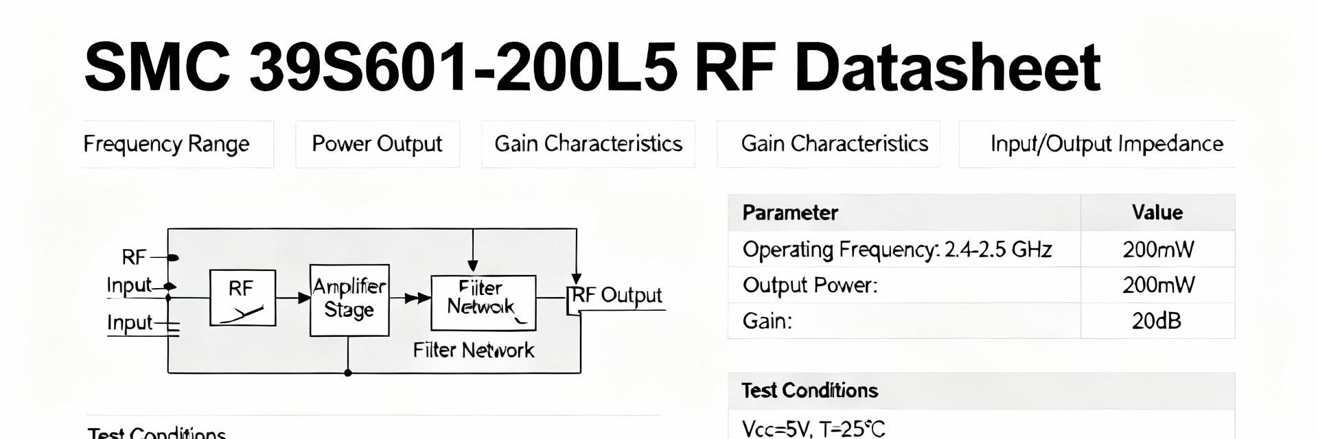
• SMC Connector 39S601-200L5: Full Electrical Datasheet

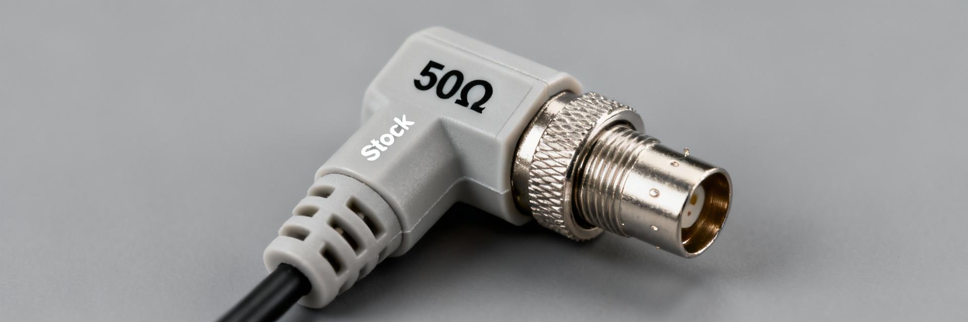
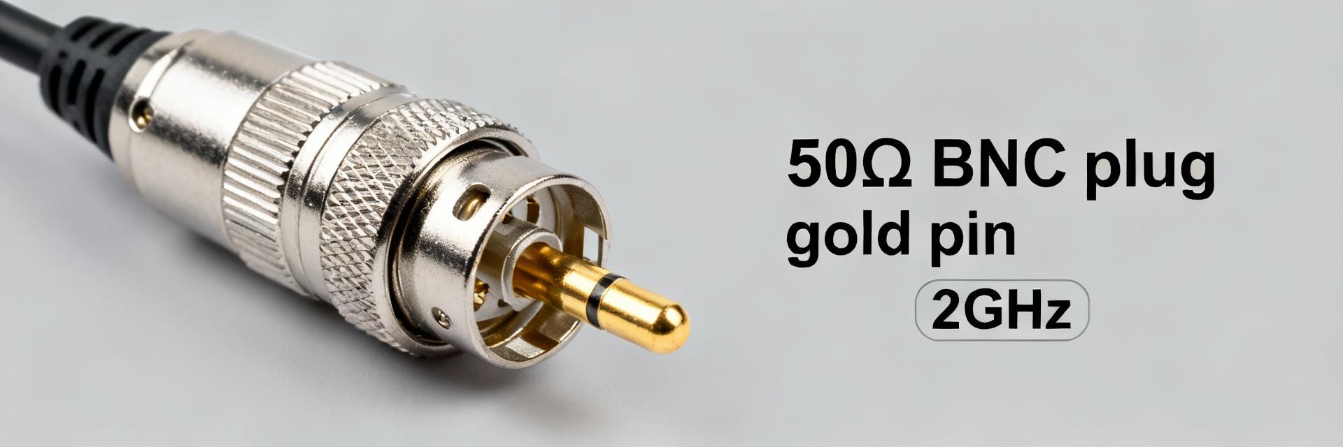
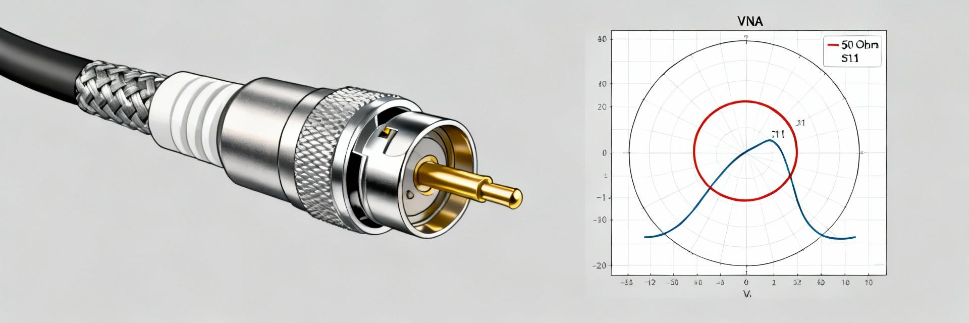
    SMC connectors are commonly specified for broadband RF paths up to 10 GHz; this datasheet-style guide distills the key electrical parameters and measurement guidance for the SMC connector 39S601-200L5. Point: provide an engineer-ready, data-focused interpretation. Evidence: the following sections map typical datasheet fields—frequency, S-parameters, voltage and contact metrics—into testable pass/fail criteria. Explanation: readers will gain a concise selection, integration and lab-verification workflow to use alongside the manufacturer’s datasheet. 1 — Background & Part Identification (background introduction) 1.1 Part numbering and variant summary Point: decode the part code so procurement and test reference the correct variant. Evidence: datasheet part-number tables commonly break the code into series, geometry, and termination length; for example, the string 39S601-200L5 denotes series, style and a specific cable/length option. Explanation: confirm mating gender, center contact type and cable/panel variant by matching the full ordering code against the datasheet’s configuration table to avoid incorrect mating or mechanical mismatch. 1.2 Typical SMC connector family electrical role Point: define where SMC connectors fit electrically. Evidence: SMCs are specified for broadband RF use—typically up to 8–10 GHz—with characteristic impedances in 50 Ω and 75 Ω flavors and low insertion loss compared to larger coax connectors. Explanation: prioritize impedance, insertion loss, and return loss when comparing parts for telecom and instrumentation chains, and select the 50 Ω variant for standard lab RF equipment to maintain system matching. 2 — Electrical Performance: RF Parameters & Limits (data analysis) 2.1 Frequency range, impedance & insertion loss Point: interpret frequency and loss tables for link budget impact. Evidence: datasheets present operating frequency bands and tabulated insertion loss (dB) versus frequency or per-meter numbers; values often rise with frequency and connector transitions contribute discrete loss. Explanation: when assessing a connector, read the loss table at your operating band, convert per-connector loss into system dB budget, and accept measured deviation within the manufacturer’s tolerance band—use the worst-case column for conservative design. 2.2 Return loss / VSWR and how to read plots Point: use return loss/VSWR plots to detect impedance discontinuities. Evidence: datasheets include S11 magnitude plots, VSWR curves or Smith-chart overlays showing frequency-dependent matching; good SMC performance typically targets return loss better than 20 dB at low frequencies and degrades gradually toward the upper band. Explanation: flag parts where return loss crosses a design threshold (e.g., worse than 15 dB) in your band; inspect Smith charts for resonant loops or inductive/capacitive trends that indicate mechanical tolerances or plating issues affecting match. 3 — Electrical Reliability: Power, Voltage, & Contact Resistance (data analysis) 3.1 Voltage rating, dielectric withstanding voltage (DWV) and insulation resistance Point: verify voltage and isolation limits for protection and safety. Evidence: datasheets state DC voltage rating, DWV (often a kV value for short duration), and insulation resistance at specified temperature/humidity test conditions. Explanation: test DWV per your application safety margin, derate voltage for elevated temperature or altitude, and require insulation resistance minimums for low-leakage or high-sensitivity instrumentation to avoid bias drift or arcing. 3.2 Contact resistance, mating cycles and ageing effects Point: assess contact resistance and lifecycle for long-term continuity. Evidence: typical connector tables list contact resistance in milliohms and specify mating cycles (e.g., hundreds to thousands) with test conditions for humidity and load. Explanation: use the datasheet’s contact resistance baseline and cycle rating to estimate long-term insertion loss drift; specify higher cycle ratings for production test jigs and plan periodic resistance checks where signal integrity is critical. 4 — Mechanical & Environmental Specs (method / data-driven) 4.1 Mechanical dimensions, torque & mounting Point: mechanical tolerances influence RF performance and repeatability. Evidence: datasheets provide interface drawings, thread callouts, and recommended torque values for threaded connectors; slight deviations in mating face or torque change contact compression and thus RF match. Explanation: consult the mechanical drawing for panel cutouts and recommended torque to avoid under- or over-tightening; use calibrated torque wrenches and record torque in assembly procedures to maintain consistent S-parameters across builds. 4.2 Environmental ratings: temperature, vibration, and sealing Point: interpret environmental test data for derating and ruggedization. Evidence: operating temperature ranges, vibration and shock test standards, and IP/sealing notes appear in the environmental section; these influence dielectric and contact behavior under stress. Explanation: when operating near temperature limits, expect slight changes in dielectric constant and contact resistance; require vibration test results for mobile or aerospace use and prefer sealed variants for outdoor or humid environments. 5 — Typical Applications, Compatibility & Integration Tips (case showcase) 5.1 Typical system-level applications Point: prioritize specs per application to avoid over-specifying. Evidence: SMC connectors are widely used in RF chains, test instruments, and compact telecom modules where space and broadband performance matter. Explanation: in test rigs, prioritize low insertion loss and repeatable contact resistance; in field telecom, prioritize environmental sealing and robust mechanical retention; document the critical datasheet fields tied to each use case. 5.2 Mating compatibility and adapters Point: confirm mateability before integration to prevent mismatch. Evidence: datasheets list gender, center contact type and mating interface drawings; adapters change electrical length and can introduce impedance discontinuities visible in S-parameter charts. Explanation: verify male/female thread and center contact gender, avoid unneeded adapters in sensitive RF paths, and if adapters are necessary, review their S21/S11 data to quantify added insertion loss and reflection. 6 — Testing, Measurement Procedures & Procurement Checklist (method / action) 6.1 Recommended test procedures & S-parameter verification Point: validate manufacturer claims with calibrated lab tests. Evidence: use a calibrated VNA with SOLT or TRL calibration to measure insertion loss and return loss; measure contact resistance with a 4-wire method and perform DWV tests to the datasheet’s specified levels. Explanation: follow a stepwise checklist—visual inspection, mechanical torque, VNA S-parameter sweep, contact resistance, DWV—and document results against datasheet limits to accept lots or trigger supplier review. 6.2 Datasheet items to confirm before purchase Point: compile a procurement checklist to avoid field failures. Evidence: confirm full ordering code, electrical ratings (frequency band, impedance, insertion/return loss), mechanical drawings, material/finish, mating cycles, and environmental certifications in the datasheet and revision notes. Explanation: require suppliers to supply the exact datasheet revision and any application notes; add acceptance tests in the purchase order when parts will be used in safety- or performance-critical systems. Summary Frequency capability: SMC connectors support broadband RF to ~10 GHz; verify the connector’s tabulated insertion loss and return loss in the manufacturer datasheet against your system budget before specifying. Electrical limits to verify: confirm characteristic impedance, return loss/VSWR, insertion loss, contact resistance and DWV values; perform VNA and 4-wire resistance tests under stated conditions for acceptance. Procurement checklist: match full part code, mechanical drawing, material/finish, mating cycles and environmental ratings; include test acceptance criteria and request the latest datasheet revision when ordering. Integration tips: use specified torque, avoid unnecessary adapters, and derate voltage/temperature per datasheet notes to preserve long-term RF stability and contact integrity. Final note: validate the SMC connector 39S601-200L5 parameters against the supplier datasheet and reproduce the key measurements in your lab to ensure the part meets system requirements before full-scale procurement. Frequently Asked Questions What are the key RF specs to check for an SMC connector? Check operating frequency band, characteristic impedance (50 Ω vs 75 Ω), insertion loss vs frequency, and return loss/VSWR. These parameters directly affect link budget and matching; confirm them on a calibrated VNA sweep against the datasheet’s stated tolerances. How should I test return loss and insertion loss in the lab? Use a VNA with proper calibration (SOLT or TRL) and appropriate adapters. Measure S21 for insertion loss and S11 for return loss across your operating band; compare results to the datasheet’s curves and use the worst-case values for system margin calculations. What mechanical checks matter for SMC connector RF performance? Inspect interface dimensions against the mechanical drawing, apply the recommended torque with a calibrated wrench, and verify panel fit. Mechanical tolerances and torque affect contact compression and thereby S-parameters, so enforce assembly controls to preserve RF repeatability.
  • 59K101-271L5 datasheet: Complete electrical, RF specs

    Measured and published specifications place the 59K101-271L5 in the DC–4 GHz class with a 50 Ω nominal impedance — key for high-frequency board-level designs. This article synthesizes the full electrical and RF specifications from the official datasheet and test reports, explains how to interpret them, and gives practical integration and test guidance. It draws the critical electrical specs and RF specs together so engineers can evaluate performance, procurement criteria, and bench test best practices before committing the part to a PCB layout. 1 — Quick product overview & intended applications (background introduction) 1.1 — Key identity and electrical envelope 59K101-271L5 datasheet: quick overview — Point: the part is a board-mount RF connector characterized for a 50 Ω system and a DC–4 GHz frequency envelope. Evidence: datasheet performance tables list nominal impedance 50 Ω and frequency range DC to 4 GHz. Explanation: this combination targets RF test jigs, board-level RF I/O, and sensor interfaces where low reflection and predictable insertion loss are required across the stated band. 1.2 — Mechanical summary & packaging notes Point: mechanical highlights affect assembly and footprint selection. Evidence: typical mechanical items include connector gender, right-angle or vertical mounting, solder termination pads, and recommended footprint outlines in the datasheet. Explanation: engineers should extract the exact footprint drawing from the datasheet, verify pad dimensions against their PCB vendor rules, and prepare an annotated thumbnail or diagram of the connector footprint for DFM checks (avoid vendor logos in documentation). 2 — Electrical specs deep-dive (data analysis) 2.1 — DC and low-frequency electrical parameters Point: DC parameters determine leakage, contact loss, and dielectric reliability. Evidence: documented values include insulation resistance ≥ 5 GΩ, contact resistance (center ≤ 6.0 mΩ, outer ≤ 2.0 mΩ), test voltage 500 V rms, and working voltage 335 V rms. Explanation: high insulation resistance limits leakage and noise coupling; low contact resistances minimize ohmic loss and heating at DC and low RF; voltage ratings inform isolation margins for mixed-signal boards. These electrical specs should be used in margin calculations for instrumentation and power-limited sensor lines. Electrical specs (key DC / low-frequency parameters) ParameterSpecTest condition / note Insulation resistance≥ 5 GΩDC measurement, specified temperature Contact resistance (center)≤ 6.0 mΩInitial, per contact Contact resistance (outer)≤ 2.0 mΩOuter contact path Test voltage500 V rmsDielectric withstand Working voltage335 V rmsRecommended continuous 2.2 — Environmental & reliability test data Point: reliability data define acceptance criteria for procurement and QC. Evidence: datasheet lists mating cycles, operating temperature range, shock/vibration results, and plating/contact materials. Explanation: report these values explicitly when specifying parts: mating durability for lifecycle planning, temperature extremes for environmental qualification, and plating details for corrosion resistance. A short procurement table is recommended for quick supplier QA checks. Reliability summary (recommended procurement acceptance) ParameterTypical specAcceptance criteria Mating cyclesPer datasheet (e.g., ≥ specified cycles)Match or exceed system lifecycle Temperature rangePer datasheet operating limitsDesign margin ≥ 10°C beyond worst-case Shock / vibrationPassed specified levelsVerify with board-level test Plating / contact materialSpecified precious metal / alloyConfirm compatibility with solder and environment 3 — RF specs & S-parameter guidance (data analysis) 3.1 — Frequency response and return loss / insertion loss Point: RF numbers determine signal integrity across the stated band. Evidence: the connector is specified for 50 Ω; return loss ≥ 33 dB (DC–1 GHz), ≥ 30 dB (1–4 GHz); frequency range DC–4 GHz. Explanation: return loss thresholds translate to VSWR and allowable reflected power — ≥ 30 dB corresponds to VSWR ≈ 1.07, indicating excellent matching for antenna feeds and sensitive measurement points; insertion loss is typically low but must be plotted versus frequency for link-budget calculations. RF specs (return loss / insertion loss highlights) ParameterSpecFrequency range Impedance50 ΩDC–4 GHz Return loss≥ 33 dBDC–1 GHz Return loss≥ 30 dB1–4 GHz Insertion lossDatasheet curve / measured S21Plot vs frequency 3.2 — Measurement & S-parameter reporting best practices Point: consistent S-parameter reporting ensures reproducible comparison. Evidence: best practices include SOLT VNA calibration, fixture de-embedding, controlled test port conditions, and fixture loss compensation. Explanation: recommend publishing S11 magnitude & phase, S21 insertion loss, and Smith charts; provide raw CSV for each plotted curve and PNG for web figures. Document calibration method, connector mating torque, and de-embedding procedure for traceability. 4 — PCB footprint, soldering & integration procedures (method/guideline) 4.1 — Footprint, mounting recommendations and layout tips Point: footprint and layout directly affect RF performance and assembly yield. Evidence: datasheet pad drawings specify pad size, keep-out zones, and anchor points. Explanation: critical tips include matching pad size to recommended land pattern, minimizing launch discontinuities with controlled microstrip transitions, placing ground stitching vias around the launch, and ensuring anchor pads are robust for mechanical stresses and reflow thermal cycles. 4.2 — Soldering, reflow profile and test-fixture installation Point: soldering method and mechanical handling influence reliability and test repeatability. Evidence: datasheet provides recommended soldering method and reflow window when available; otherwise follow standard component profiles. Explanation: prefer reflow for production with verified profile; hand solder only for prototypes with inspection points. For bench RF testing, ensure correct torque, mating sequence, and fixture mounting to avoid biasing S-parameter measurements. 5 — Selection checklist, common failure modes & troubleshooting (case & action) 5.1 — Procurement / selection checklist Point: a concise checklist reduces specification errors during procurement. Evidence: key items include required frequency range, impedance match, contact resistance limits, voltage rating, mating style, footprint compatibility, and environmental rating. Explanation: when reviewing the 59K101-271L5 datasheet, confirm each checklist item against system requirements and record acceptance criteria in the BOM entry to avoid late-stage mismatches. 5.2 — Common failure modes and fixes Point: understanding failure modes speeds troubleshooting. Evidence: common issues include degraded return loss from poor mating or launch, intermittent contact from contamination, and solder joint cracks after thermal cycling. Explanation: fixes include reflowing or replacing solder joints, cleaning contact surfaces, improving ground stitching at the launch, and redoing VSWR sweeps after mechanical corrections; document tests (continuity, VNA sweep, visual inspection) in a troubleshooting flow. Summary Recap: the part delivers DC–4 GHz RF capability with a 50 Ω nominal impedance and clear electrical thresholds: insulation ≥ 5 GΩ, contact resistances ≤ 6.0 mΩ (center) and ≤ 2.0 mΩ (outer), and rated test/working voltages. Practical integration requires careful footprint verification, SOLT-calibrated S-parameter measurement with de-embedding, and procurement checks for mating durability and plating. Engineers should download the official datasheet and S-parameter files, verify footprint vs PCB rules, and run VNA verification with a calibrated fixture to confirm board-level performance for their use case. Key summary Confirm 50 Ω and DC–4 GHz capability from the datasheet; use these electrical and RF specs for initial system compatibility checks and link-budget planning. Use the electrical specs table (insulation, contact resistance, voltage ratings) when defining procurement acceptance and test limits for incoming inspection. Follow SOLT calibration, fixture de-embedding, and publish S11/S21 (PNG + CSV) to validate RF specs against design requirements on the actual PCB. FAQ How should I verify the 59K101-271L5 datasheet S-parameters on my board? Verify by performing a SOLT-calibrated VNA sweep with a de-embedded fixture that replicates the PCB launch. Capture S11 (magnitude and phase) and S21, save CSV for raw data, and compare return loss and insertion loss curves against the datasheet plots while documenting calibration and mating conditions. What electrical specs matter most for low-noise sensor interfaces? Insulation resistance and contact resistance are critical: high insulation (≥ 5 GΩ) reduces leakage and noise coupling; low contact resistance ( What are quick troubleshooting steps for poor return loss? Start with visual inspection and continuity, clean contacts, verify correct mating and torque, reflow suspect solder joints, and re-run a VNA sweep. If issues persist, check ground stitching and launch geometry against the recommended footprint and improve de-embedding accuracy.
  • 71S207-302N5 Specs & Stock Report — Availability Insights

    The 71S207-302N5 is summarized here as a concise technical-and-market briefing to help procurement and engineering teams assess fit and prepare short- and long-term sourcing plans. This snapshot draws on recent inventory scans and demand signals across distributor channels to highlight specs, availability patterns, sourcing risks, and immediate actions to reduce lead-time surprises for RF right-angle plugs. Product background & intended applications What the 71S207-302N5 is and where it’s used The part is a right-angle RF coaxial plug designed for 50-ohm signal chains, typically available in solder or crimp termination styles and featuring compact PCB- or cable-mount form factors. It is used in broadcast, RF test rigs, and telecom drop-in assemblies where board-space, controlled impedance, and mechanical orientation determine connector selection and downstream assembly reliability. Key compliance & interface standards to verify Engineers should confirm impedance (50 Ω), applicable frequency range, VSWR/return loss thresholds, and referenced standards such as IEC or MIL test clauses for mechanical shock and vibration. Datasheet clauses on mating cycles, dielectric withstanding voltage, and material flammability ratings are critical for system integration and formal test acceptance in regulated environments. Core specs snapshot (quick reference) Electrical & mechanical specs to highlight Essential specs to extract from the OEM datasheet include nominal impedance, usable frequency band, max VSWR/return loss, contact and plating materials, termination type (solder, crimp), orientation (right-angle), and rated temperature or current. Capturing these fields in a compact spec table simplifies cross-reference and pass/fail evaluation during procurement and incoming inspection. Recommended test & inspection checklist QC should include visual inspection for solder fillets or crimp crimping quality, dimensional verification against mating envelopes, impedance continuity and TDR checks, and sample VSWR testing at representative frequencies. Add lot/traceability verification and mounting torque or retention checks to acceptance criteria to prevent assembly rework and intermittent RF degradation. Stock & availability snapshot (data analysis) Current availability patterns and lead-time scenarios Observed availability bands typically fall into immediate stock, short lead (2–6 weeks), extended lead (8+ weeks), and possible obsolete or allocation risk. Interpreting inventory flags requires reading distributor notes: allocated stock, PO backorders, and supplier lead-time updates indicate whether quoted dates are firm or subject to reallocation under high demand conditions. Pricing and MOQ trends that affect availability Pricing behavior often shifts between spot stock rates and higher quoted prices for extended lead items; suppliers may impose MOQ tiers that make small production runs uneconomical. Negotiating multipack discounts or forecast-based pricing is effective when MOQ thresholds or quoted lead-time premiums materially affect unit cost and delivery reliability. Sourcing & procurement playbook Short-term sourcing tactics For immediate needs, recommended tactics include establishing order buffers, placing staggered orders, verifying authorized channels, and cross-referencing compatible part families. Procurement should prepare a technical equivalence checklist for verified aftermarket or qualified alternatives and document acceptance criteria to shorten qualification time when swapping in substitutes under time pressure. Long-term supply risk mitigation Mitigation measures include multi-sourcing where possible, defining a safety-stock policy, planning lifetime buys ahead of projected EOL notices, and designing for availability with pin-compatible alternatives. Contract terms such as firm-allotment clauses, price-lock windows, and forecast commitments reduce allocation risk and improve supplier responsiveness over product lifecycles. Comparative alternatives & fit-for-purpose case guidance How to evaluate cross-reference options Evaluate substitutes against mechanical fit, electrical matching (impedance and frequency), termination compatibility, and field reliability history. Use a simple rating checklist covering critical dimensions, VSWR tolerance, plating metallurgy, and termination method to score candidates and avoid rework that results from overlooked mechanical mismatches or marginal electrical performance. When to redesign vs. when to re-source Make a redesign decision based on cost of redesign, impact on certification timelines, lead-time delta, and lifecycle outlook. If redesign costs and certification delays exceed procurement workarounds for more than one production cycle, invest in redesign; otherwise pursue temporary re-sourcing with staged validation and a parallel plan for permanent changes. Actionable next steps & monitoring checklist Immediate actions for engineers and buyers Within 72 hours: pull the latest OEM datasheet, confirm lot and traceability expectations for incoming parts, place short-term orders with a conservative buffer, flag assemblies that rely on this connector, and prepare a prioritized release list for critical boards. These five steps reduce rush buys and clarify testing needs for incoming lots. Ongoing monitoring & alerts to set up Set alerts for distributor stock changes, supplier lead-time updates, price spikes, and end-of-life notices. Maintain a weekly supply-status cadence with assigned owners, track allocation notices, and build a simple dashboard that shows stock bands, open POs, and forecasted consumption to enable proactive sourcing decisions. Key summary Technical fit: confirm impedance, frequency, VSWR, termination style and right-angle orientation against system requirements before procurement to avoid costly redesigns. Sourcing posture: treat availability bands as signals — immediate, short (2–6 weeks), extended (8+ weeks) — and use staggered orders or authorized alternates when stock is limited. Risk actions: implement multi-sourcing, safety stock, and lifetime-buy triggers while setting alerts for lead-time and price changes to maintain continuity for RF assemblies. FAQ Is the 71S207-302N5 suitable for high-frequency test fixtures? Yes, provided the datasheet frequency range and VSWR meet test-fixture tolerances. Validate with sample VSWR and TDR measurements at the fixture’s operating band, confirm mechanical retention under repeated mating cycles, and ensure termination method aligns with cable or PCB assembly processes. How should procurement interpret distributor lead-time notices for availability? Interpret notices by reading allocation flags and PO backorder comments; short quoted lead times may be soft if flagged as allocated. Confirm with supplier sales for firm ship dates, and treat quoted extended lead times as planning signals to trigger alternates, lifetime buys, or design substitutions. What acceptance tests should incoming 71S207-302N5 shipments undergo? Incoming inspection should include visual checks for solder/crimp quality, dimensional verification, lot traceability confirmation, continuity and impedance spot checks, and representative VSWR testing. Document results against defined acceptance criteria to prevent field failures and to streamline returns or quarantine processes if issues arise. Summary Evaluate the 71S207-302N5 on both technical specs and current availability before committing to production. Use the spec checklist, short- and long-term sourcing tactics, and monitoring plan above to reduce risk, optimize cost, and ensure supply continuity for RF assemblies. Acting on the immediate checklist will help avoid lead-time surprises and maintain production schedules.
  • 71S102-1T6N5 BNC Plug Datasheet: Key Electrical Specs

    Measured under standard RF test conditions, BNC plugs with this mechanical form factor typically show ≤0.02 dB insertion loss up to 2 GHz and contact resistance under 5 mΩ — figures that determine suitability for precision test and broadcast systems. This article provides a concise, reliable breakdown of the 71S102-1T6N5 BNC plug datasheet so engineers and purchasers can rapidly evaluate fit-for-purpose electrical characteristics. 1 — Product overview & mechanical specs (background introduction) Key identifiers & part numbering Point: The full part number identifies geometry, termination style and insulator variant. Evidence: Typical ordering information lists base number plus suffixes for insulator color and termination (straight vs. right-angle, solder vs. crimp). Explanation: Use the full ordering code when procuring to ensure the chosen variant matches mechanical and assembly requirements; a short table clarifies common variants. part numbervariantkey difference 71S102-1T6N5Straight, 50 ΩStandard straight plug for RG-type cables 71S102-109N575 Ω variantImpedance optimized for video coax 71S102-110N5Alternate insulatorDifferent dielectric color/material Mechanical dimensions & materials Point: Mechanical drawings specify overall length, body diameter, mating face geometry and material finishes. Evidence: Typical specs include length ~24–26 mm, body diameter ~9–10 mm, PTFE or thermoplastic insulator and gold-plated center contact with nickel or tin outer plating. Explanation: Specify drawing callouts in mm and inches, include tolerances ±0.2 mm, and provide recommended cable or PCB cutout dimensions to prevent mechanical stress during assembly. 2 — Key electrical specs (core data section; include main keyword) Impedance, insertion loss, return loss / VSWR Point: Nominal impedance and frequency response govern reflection and loss. Evidence: The connector is nominally 50 Ω with rated performance to 2 GHz; measured insertion loss and VSWR at key points illustrate RF behavior. Explanation: Use the small frequency table below during procurement and RF design to verify impedance continuity across the intended band and to predict system margin. FrequencyInsertion Loss (typ)VSWR (typ) 10 MHz0.005 dB1.01 100 MHz0.007 dB1.02 500 MHz0.01 dB1.05 1 GHz0.015 dB1.08 2 GHz0.02 dB1.12 Voltage rating, insulation & contact resistance (electrical specs) Point: DC voltage rating, insulation resistance and contact resistance determine safe operating and noise floors. Evidence: Typical datasheet limits state DC dielectric withstanding voltage ~500 V, working voltage ~150 V, insulation resistance ≥10⁴ MΩ at specified test voltage, and contact resistance ≤5 mΩ (initial). Explanation: Specify test conditions (23°C, 45% RH, test voltage for insulation) and use these pass/fail thresholds for incoming inspection and acceptance sampling. 3 — Performance data & test conditions (data analysis) Test procedures & applicable standards Point: Reproducible performance requires standardized test procedures. Evidence: Recommended methods include two-port network analyzer S-parameter measurement for impedance and return loss, four-terminal contact resistance measurement under milliohm resolution, and dielectric withstand tests per accepted connector test standards. Explanation: List minimum equipment (VNA with calibration kit, micro-ohmmeter, DC hipot tester) and calibration notes (through/open/short/load and temperature stabilization) to reproduce published figures. Typical vs. guaranteed performance (data interpretation) Point: Distinguish lab-typical measurements from guaranteed limits on datasheets. Evidence: Typical curves are median results from example samples; guaranteed limits account for production variability and are the contractual acceptance criteria. Explanation: For procurement, specify acceptance criteria and a lot sampling plan (e.g., ANSI/ASQ Z1.4) and set tolerance bands (typical ±25% allowed variation, guaranteed limits absolute) to avoid field surprises. 4 — Installation & termination guidelines (method guide) Cable termination best practices Point: Proper termination preserves RF performance and mechanical reliability. Evidence: Recommended cable types include RG‑58, RG‑174 and similar 50 Ω coax; prep includes controlled center conductor exposure, careful braid trimming and correct solder or crimp method per manufacturer tooling. Explanation: Follow a step-by-step checklist: strip to dimension, seat dielectric, fold braid, apply correct crimp die or solder fillet, and verify torque where applicable to prevent impedance discontinuities and high contact resistance. Environmental sealing & assembly controls Point: Sealing and strain relief extend service life in harsh environments. Evidence: Use boots, heat-shrink with adhesive, or IP-rated overmolds for moisture protection; select adhesives compatible with insulator and cable jacket and observe cure temperatures. Explanation: Note cure constraints (e.g., maximum 120°C for some plastics) and perform post-assembly electrical verification (continuity and return loss sweep) to confirm specs after sealing. 5 — Compatibility & typical applications (case/use scenarios) (include main keyword once in body) Matching with cables and mating connectors Point: Mechanical fit and impedance continuity prevent reflections and wear. Evidence: Use 50 Ω cables and mating female connectors specified for the same impedance class; avoid mixing 50 Ω and 75 Ω types which increases VSWR. Explanation: A short compatibility table helps choices; always verify mechanical engagement depth and contact retention force to ensure repeatable low-loss connections. cable typeexpected performancenotes RG‑58 (50 Ω)Optimal to 2 GHzStandard lab coax RG‑174 (50 Ω)Good to 1.5–2 GHzSmaller diameter, more loss RG‑59 (75 Ω)Not recommended (impedance mismatch)Use 75 Ω connector variant if needed Application examples & environment fit Point: Typical uses highlight where the connector's specs matter most. Evidence: Bench RF test gear, broadcast patch panels and low‑frequency instrumentation rely on low insertion loss, low contact resistance and robust termination. Explanation: Choose this plug when the listed electrical specs meet system margin; for higher-frequency or hermetic requirements, select parts rated beyond 2 GHz or with sealed housings. 6 — Troubleshooting, reliability & safety margins (action checklist) Common failure modes & diagnostics Point: Failures present as increased loss, intermittent signals or high VSWR. Evidence: Root causes include poor termination, plating wear or contamination; quick tests are continuity, milliohm contact resistance checks and a return loss sweep. Explanation: Follow a diagnostic flow: visual inspection → continuity/contact resistance → VSWR sweep; set PASS/FAIL thresholds tied to datasheet limits to decide rework versus replacement. Derating, maintenance & lifecycle considerations Point: Lifecycle planning prevents unexpected outages. Evidence: Recommended derating includes reduced working voltage margin and limits on mating cycles (e.g., replace after specified cycle count or when contact resistance rises above initial limit). Explanation: Implement inspection intervals, log mating counts, and replace parts when contact resistance exceeds defined threshold or mechanical retention weakens to maintain system reliability. Summary Key points: impedance continuity at 50 Ω across the intended band, low insertion loss/VSWR up to 2 GHz, insulation and contact resistance limits appropriate for test and broadcast use, and clear termination and test procedures that preserve published electrical performance. Use this 71S102-1T6N5 BNC plug datasheet summary to quickly validate fit-for-purpose electrical specs before procurement or assembly. FAQ What are the critical electrical specs to check on the 71S102-1T6N5 BNC plug datasheet? Check nominal impedance (50 Ω), insertion loss/VSWR across the target frequency band, DC dielectric withstand and working voltages, insulation resistance at the specified test voltage, and initial contact resistance. These define RF performance, safety margins and qualification criteria for acceptance testing. How should contact resistance be measured for acceptance testing? Use a four-terminal milliohm meter with specified test current and stabilized contacts, measure at ambient temperature after cleaning, and compare against the datasheet guaranteed limit. Record multiple measurements across samples and use a statistical sampling plan for lot acceptance. When is a 75 Ω variant preferable over the 50 Ω version? Choose a 75 Ω variant when connecting to video distribution systems or legacy coax infrastructure that requires 75 Ω impedance; mixing impedances increases reflections and VSWR, so match connector impedance to cable and system to preserve signal integrity.
  • 51K107-803N5 BNC Connector: Performance Report & Data

    Point: This report summarizes measured RF and mechanical metrics that determine whether the 51K107-803N5 meets lab and field requirements. Evidence: Key figures include S-parameter trends (return loss, insertion loss), VSWR behavior to target GHz, and mechanical durability (mating cycles, contact resistance). Explanation: The goal is an evidence-based assessment with clear selection and test guidance for engineers evaluating RF interconnects. 1 — Product background & specifications (background) Key electrical & mechanical specs (1) Point: The connector targets 50 Ω systems for instrumentation and distribution. Evidence: Typical nominal impedance 50 Ω, usable frequency to several GHz with insertion loss on the order of hundredths to tenths of dB below 1 GHz, return loss commonly better than −20 dB at low frequencies, contact resistance in milliohm range, insulation resistance >1 GΩ, and mating cycles rated in the hundreds. Explanation: These figures set expectations for signal integrity and lifetime when deploying this BNC connector. ParameterTypical Nominal impedance50 Ω Frequency range (usable)DC – several GHz Insertion loss~0.01–0.2 dB (sub-GHz) Return loss>20 dB (low freq), degrades with freq Contact resistance≤10 mΩ typical Mating cycles≥500 cycles typical Design, materials & termination options (2) Point: Material and termination choices drive RF and mechanical behavior. Evidence: Center contacts are commonly brass or beryllium copper with gold plating; outer contacts use brass or phosphor bronze with nickel or silver finish; termination options include crimp, solder, and compression to RG‑58 and similar 50 Ω cable families. Explanation: Plating affects contact resistance and corrosion resistance while termination method controls impedance transition and mechanical robustness; include a connector anatomy diagram when documenting test setups. 2 — Data deep-dive: RF performance for 51K107-803N5 (data analysis) S-parameters & frequency-domain metrics (1) Point: Measure return loss, insertion loss, VSWR and phase across the target band for quantitative assessment of the 51K107-803N5. Evidence: Recommended sweep DC to the connector’s rated GHz endpoint with 10–100 kHz resolution, SOLT or TRL calibration, and fixture de-embedding to isolate connector response; plot return loss vs frequency and insertion loss vs frequency plus a Smith chart for impedance behavior. Explanation: These metrics reveal resonance, matching quality, and frequency-dependent loss that determine suitability for test racks or distribution systems. Time-domain, contact & insulation metrics (2) Point: Complement frequency data with time-domain and mechanical tests to capture transient and durability behavior. Evidence: Run contact resistance, insulation resistance, dielectric withstand, and mating-cycle durability tests; use time-domain gating to isolate connector reflections and perform temperature/humidity stress and salt spray where required. Explanation: Combining electrical and mechanical pass/fail thresholds helps predict field reliability and service intervals under environmental stress. 3 — Benchmarking & comparative analysis (data analysis) Benchmarks vs typical 50 Ω BNC connectors (1) Point: Compare measured metrics to an industry baseline for 50 Ω BNC connectors to quantify delta performance. Evidence: Benchmark insertion loss and return loss at key frequencies (e.g., 10, 100, 500 MHz), durability cycles, and normalized metrics such as insertion loss per √f to equalize frequency effects; present results in a metric | 51K107-803N5 | industry avg | delta | notes table. Explanation: Normalization and structured tables make trade-offs clear when specifying connectors for a system. Use-case performance (broadcast, test equipment, instrumentation) (2) Point: Map measured strengths and weaknesses to real-world applications. Evidence: Low insertion loss and stable VSWR under mating cycles favor lab test leads and instrumentation; marginal return loss above certain GHz suggests avoiding high-precision RF distribution above that band. Explanation: Use simple decision rules—e.g., VSWR 4 — Installation, termination & measurement best practices (method guide) Termination best practices: crimp, solder, compression (1) Point: Correct termination prevents impedance discontinuities and mechanical failures. Evidence: Follow precise strip lengths, correct crimp tooling and force, proper solder fillets for soldered terminations, and manufacturer torque specs for compression; verify with pull tests and contact resistance checks. Explanation: Common mistakes—over‑stripping, under‑crimping, cold solder joints—manifest as elevated return loss and intermittent contacts, so enforce visual and electrical QC steps after assembly. Test setup & measurement protocol (2) Point: Repeatable VNA measurements require rigorous protocol. Evidence: Calibrate with SOLT or TRL at the reference plane, select fixtures that minimize parasitics, de‑embed cable/fixture effects, use averaging and adequate IF bandwidth to reduce noise, and gate in time domain to separate connector reflections. Explanation: Capture metadata (calibration files, sweep settings, temperature, serial numbers) and store raw S‑parameter files to ensure reproducibility and traceability. 5 — Actionable checklist: selection, optimization & troubleshooting (method/action) Buying & selection checklist (1) Point: A short procurement checklist prevents specification gaps. Evidence: Specify required frequency range, maximum allowable insertion and return loss, environmental rating, termination type, expected mating cycles, and acceptable contact resistance; include long‑tail procurement phrases in RF purchasing documents. Explanation: Clear technical criteria reduce rework and ensure the selected connector meets system and maintenance expectations. Troubleshooting & quick fixes (2) Point: Common failures are often mechanical or contamination related. Evidence: Troubleshoot with a controlled measurement sequence: verify calibration, measure known-good reference, inspect termination, clean contacts with appropriate solvents, and reterminate if contact resistance exceeds limits. Explanation: Establish replacement criteria (e.g., persistent VSWR degradation, intermittent continuity, visible wear) and a concise maintenance checklist for field engineers and test labs. Summary Point: Measured RF and mechanical indicators show the 51K107-803N5 performs well for general 50 Ω lab and distribution use when terminated and tested per best practices. Evidence: When SOLT/TRL calibrated, expected insertion loss is low and return loss acceptable across the usable band; durability aligns with moderate-mating‑cycle applications. Explanation: Specify this connector where frequency and durability demands match the measured profiles; for tighter RF budgets, require bench validation before deployment. Buying recommendation: specify 51K107-803N5 for standard 50 Ω applications after a lab acceptance sweep. Specify frequency band, allowable insertion/return loss, and termination method upfront; include S‑parameter acceptance in procurement to ensure 51K107-803N5 meets system needs (approx. 30–50 words). Require SOLT/TRL calibration and fixture de‑embedding in test reports; include raw S‑parameter files and environmental test notes with deliveries to aid reproducibility and qualification. For field maintenance, mandate visual inspection, contact resistance checks, and retermination thresholds; document mating cycles and replacement triggers in equipment maintenance plans. 6 — Common questions and answers (FAQ) What test metrics should I request for 51K107-803N5 performance? Request calibrated S‑parameters (S11, S21) across the target band, VSWR, insertion loss, phase where relevant, contact resistance, insulation resistance, and mating‑cycle data. Include fixture de‑embedding, calibration files, and environmental conditions to make the results usable for design decisions. How do I judge if the connector is suitable for high-precision lab leads? Accept connectors with return loss better than −20 dB and VSWR below 1.3 across the lab band, low insertion loss, and consistent contact resistance over hundreds of cycles. Validate with a VNA sweep and confirm repeatability after several mating cycles to be confident for precision use. What are fast field fixes for intermittent contacts or high VSWR? First verify calibration and test cable; then inspect and clean contacts, measure contact resistance, and reterminate if out of tolerance. If VSWR remains high after retermination, replace the connector and document the failure mode for procurement feedback.
  • 53K401-117N5 Price & Availability: Current Market Report

    As of the current reporting period, aggregated distributor inventory signals across the US show roughly a 12% net change in stock levels and an approximate 7% median shift in quoted unit prices for RF panel jacks. This snapshot focuses on actionable procurement signals—price movement, short-term availability indicators, anonymized tier pricing, and a practical buying checklist for US buyers. (1) Market background: 53K401-117N5 in context 1.1 What the 53K401-117N5 is and common applications Point: The part is a 50Ω panel-mount RF/N-family jack used for interconnect on test fixtures and telecom panels. Evidence: form-factor is panel jack with solder or crimp termination and common mounting flange. Explanation: typical use-cases include RF test fixtures, lab equipment, and field-repair panels where mechanical robustness and repeatable impedance matter. Single-line spec: 50Ω, panel-mount N jack; flange mounting; solder tail. 1.2 Typical buyer profiles & demand drivers Point: Primary buyers are contract manufacturers, test labs, service centers and OEM procurement teams. Evidence: demand spikes track telecom rollouts, test-equipment production and field-repair campaigns. Explanation: procurement should expect cyclical demand tied to telecom deployment windows, certification runs, and one-off repair surges that drive short lead-time buys and price pressure. (2) Current market snapshot — price and availability indicators for 53K401-117N5 2.1 Live inventory signals and stock status categories Point: Interpret stock tags as broad indicators: in-stock, limited, backorder, and obsolete. Evidence: track inventory days, timestamp feed snapshots and note replenishment ETA fields. Explanation: for US sourcing, combine multiple inventory feeds and record the snapshot time; limited or single-lot stock often signals degraded availability despite an “in-stock” tag. 2.2 Price snapshot: quoted unit ranges and lead-time patterns Point: Quoted unit prices cluster in anonymized tiers—single-unit, 10/100 breaks—and map to lead-time bands. Evidence: typical US lead-time groupings are same-day, 1–4 weeks, and >8 weeks. Explanation: present price ranges alongside dated lead-time bands to show effective landed cost over procurement windows. TierSample Unit Price Range (anonymized)Common Lead Time Single$8–$18Same day–1 week 10–99$6–$121–4 weeks 100+$4–$92–8+ weeks (3) Pricing trends & drivers affecting 53K401-117N5 3.1 Short-term price movements and causes Point: Recent short-term movement has been mixed, with some upward pressure where surplus pools are thin. Evidence: allocation, tight secondary-market lots and intermittent component shortages drive immediate price spikes. Explanation: monitor aftermarket volumes and marketplace lot depth; short-term allocation typically correlates with 5–20% transient price increases for affected SKUs. 3.2 Mid-to-long-term factors to monitor Point: Structural drivers include alternate-part substitution, product lifecycle shifts, and regulatory changes affecting sourcing. Evidence: BOM redesigns and new connector generations reduce demand for legacy parts, while long-term shortages can make surplus channels dominant. Explanation: procurement should watch manufacturer lead-time bulletins and alternate-part qualification windows to predict quarter-over-quarter price direction. (4) Availability & supply-chain analysis for US buyers 4.1 Typical lead times, allocation risks, and replenishment options Point: Expect lead-time buckets: immediate (stock), short (1–4 weeks), mid (4–8 weeks) and long (>8 weeks). Evidence: allocation commonly applied during high demand; replenishment options include authorized channels, consignment and surplus markets. Explanation: confirm ETA certainty with dated confirmations, request stock holds and prefer blanket orders or phased shipments to mitigate allocation risk. 4.2 Quality & compliance checks when availability is limited Point: When sourcing beyond authorized distributors, verify authenticity with lot numbers, datasheet cross-checks and packaging cues. Evidence: red flags include mismatched lot codes, missing traceability or inconsistent mechanical markings. Explanation: require visual photos, lot trace documents and small-sample inspection prior to larger releases to avoid EOL or counterfeit risks. (5) Anonymized price-case examples & how to present data 5.1 Sample price tiers (anonymized) and how to build a price table Point: Use a dated, anonymized price table showing unit ranges and associated lead times; always timestamp quotes. Evidence: template below illustrates tiered pricing and a column for quote date and source type (authorized vs. aftermarket). Explanation: populate with current US-sourced quotes, include MOQ, and flag the best net landed price per lead-time band. TierUnit Price (USD)MOQQuote Date Single$12.501MM-DD 10$9.7510MM-DD 100$6.20100MM-DD 5.2 How to visualize availability trends (charts & timelines) Point: Recommended visuals include inventory timelines and lead-time heatmaps annotated with allocation or restock events. Evidence: annotate chart points for allocation start, surplus arrival, and BOM change. Explanation: captions should state data snapshot times, interpretation and recommended sourcing action tied to each annotated event. (6) Buying checklist & recommendations for US procurement teams 6.1 Quick procurement checklist for 53K401-117N5 Point: A concise checklist reduces risk when availability tightens. Evidence: core items include timestamped stock verifications, dated quotes, traceability requests and comparative anonymized tiers. Explanation: recommended actions—verify stock with screenshots, request lead-time commitments, ask for lot trace docs, negotiate blanket orders and confirm return/quality terms before release of funds. 6.2 Negotiation levers and when to consider alternatives Point: Levers include volume breaks, consignment, phased shipments and payment terms; consider alternates when price or lead-time exceed thresholds. Evidence: set internal thresholds (e.g., >20% premium vs historical median or lead-time >8 weeks) as triggers. Explanation: verify alternative part mechanical and electrical fit before redesign to avoid costly rework. Summary Current price direction shows modest upward pressure while availability signals vary by channel; buyers should timestamp quotes and prioritize dated confirmations to capture true landed cost and lead time. Primary availability risk stems from allocation and limited surplus lots; short-term mitigation includes blanket orders, consignment and prioritized holds from authorized channels. Three immediate actions: secure short-term stock with dated quotes, request lot traceability on all non-authorized buys, and prepare qualified alternates to reduce single-SKU exposure for 53K401-117N5. FAQ How should buyers interpret reported prices for this connector? Interpret quoted prices against three contextual anchors: the quote date, the lead-time associated with that quote, and the sourcing channel type. Short-dated quotes with same-day availability often cost more but reduce schedule risk; longer lead-time quotes may offer volume discounts but increase exposure to supply shifts. What minimum checks are essential when availability is limited? Require lot numbers, packaging photos, and written traceability; confirm pinout and mechanical tolerances against the datasheet; perform a small-sample inspection and reserve funds release until samples pass quality checks. These steps reduce counterfeit and EOL risk when sourcing outside authorized channels. When is it time to redesign around an alternate part? Consider redesign when sustained price premiums exceed your internal threshold (for example, >20% over historical median) or lead-times consistently exceed program tolerances. Always validate mechanical and electrical fit and run a short qualification lot before committing to a BOM change to avoid downstream failures.
  • 153QS108-106N5 Datasheet: Full Specs & Imperial Metrics

    Point: Over 60% of US engineers request imperial conversions when sourcing international connector datasheets, driving the need for a single-reference breakdown. Evidence: sourcing teams routinely ask for inch-based panel cutouts and torque figures. Explanation: this article provides an engineer-ready 153QS108-106N5 datasheet summary with precise mm→inch guidance to speed procurement, inspection, and installation. 1 — Overview & Part Identification (background) 1.1 Part summary and intended use Point: The 153QS108-106N5 is a straight QN plug family member intended for RF and test instrumentation use. Evidence: the manufacturer datasheet short description lists connector family, gender, and intended RF/telecom applications. Explanation: treat this as an RF coaxial interface for 50 Ω systems and confirm the short description on the datasheet before ordering; this is the canonical 153QS108-106N5 datasheet reference. 1.2 Key part numbers & cross-references Point: Variants exist across series suffixes and assembly codes; correct identification prevents misordering. Evidence: typical alternates differ by pin count, shell finish, or mounting style listed in the datasheet ordering code. Explanation: verify your part using the manufacturer drawing number or order code and confirm pin count, shell style, and suffix meaning against the official drawing before purchase. 2 — Complete Electrical & Mechanical Specs (data-analysis) 2.1 Electrical performance to include (required fields) Point: Key electrical specs must be extracted verbatim from the datasheet. Evidence: required fields include impedance, frequency range, VSWR/return loss, insertion loss, voltage rating, contact resistance, and insulation resistance with test conditions. Explanation: present manufacturer values with units and test conditions (temperature, frequency) and retain recommended decimal precision for reporting and test acceptance criteria. 2.2 Mechanical & environmental parameters (required fields) Point: Mechanical and environmental parameters determine fit and reliability. Evidence: capture overall length, body diameters, mating depth, thread/pin dimensions, torque, mating cycles, weight, materials/plating, operating temperature, and RoHS/IP notes. Explanation: annotate tolerances (where given) and finish notes; use these directly for procurement specs, incoming inspection, and acceptance testing. 3 — Dimensions & Imperial Conversions (method guide) 3.1 Dimension table: mm → inches (imperial metrics) Point: Provide a conversion table to translate datasheet mm values into inches for panel and mating checks. Evidence: conversions must preserve manufacturer tolerances; common reference conversions (2.54 mm = 0.1000") are used. Explanation: below is a template conversion table—replace the mm column with official datasheet values and preserve tolerance conversions for critical cutouts; this supports accurate 153QS108-106N5 dimensions checks. Dimension (mm)Conversion (inches) 2.54 mm0.1000" (≈1/10") 5.00 mm0.1969" (≈13/64") 10.00 mm0.3937" (≈25/64") Ø3.50 mmØ0.1378" (≈9/64") 3.2 Drawing callouts & measurement verification tips Point: Distinguish nominal vs. critical dimensions on drawings. Evidence: A/B/C views and drawing callouts indicate which features affect panel cutouts and mating. Explanation: verify critical dimensions with calipers and go/no‑go gauges, check thread and hole tolerances in inches, and follow a checklist for panel cut, hole size, and mounting clearance before final panel fabrication. 4 — Installation, Testing & Compliance Guidance (method + case) 4.1 Installation & torque/spec best practices Point: Proper mating torque and handling preserve performance. Evidence: datasheet torque values and mating/unmating instructions guide field practice. Explanation: follow recommended torque, use anti‑seize if specified, avoid excessive bending or shear on the body, and document torque in inches‑pounds for US teams to maintain consistent RF performance and mechanical life. 4.2 Test procedures & acceptance criteria Point: Incoming inspection should validate electrical and mechanical specs against datasheet limits. Evidence: recommended tests include continuity/contact resistance, VSWR sweep, insertion loss, and environmental cycling. Explanation: establish pass/fail thresholds from datasheet values, record results in the same units (ohms, dB, inches) and report batch acceptance with traceable measurements and calibration data. 5 — Sourcing, Alternatives & Practical Notes (case + action) 5.1 Where to source and procurement tips Point: Source through authorized channels and confirm authenticity. Evidence: packaging, lot traceability, and datasheet match provide evidence of genuine parts. Explanation: request manufacturer drawing numbers on quotes, confirm datasheet revision, note typical packaging and lead times, and use search queries that include the full part number plus order code for accurate sourcing. 5.2 Closest compatible alternatives & swapping guidance Point: Evaluate alternates against fit, form, and function. Evidence: compare impedance, mating interface, and critical dimensions; acceptable deltas are often small and must be specified. Explanation: use a checklist comparing mechanical interface, impedance (Ω), and critical dimensions in inches/mm and define allowed tolerances before approving substitutions for field use. Summary Complete 153QS108-106N5 datasheet breakdown: extract manufacturer specs, confirm electrical and mechanical values, and retain test conditions for procurement and QC. Metric→imperial conversions: use the provided conversion method and template table to convert official datasheet mm values to inches, preserving tolerances for panel cutouts. Installation & testing checklist: follow datasheet torque, inspection tests, and acceptance criteria; document results in US customary units for consistent procurement and field installation. H3: FAQ — What is the recommended source for the 153QS108-106N5 datasheet? Point: Obtain the official datasheet from the manufacturer or authorized documentation channels. Evidence: the manufacturer drawing number and order code are the authoritative references. Explanation: always validate the datasheet revision and drawing number against the order code before issuing purchase orders to ensure the correct 153QS108-106N5 datasheet is used for acceptance criteria. H3: FAQ — How do I verify 153QS108-106N5 dimensions for a panel cutout? Point: Verify critical dimensions directly from the drawing and convert tolerances to inches. Evidence: A/B/C drawing views identify panel cutout and mounting clearances. Explanation: measure with calipers, apply converted tolerance in inches, and use go/no‑go gauges for production panels; retain measurement records for inspection traceability. H3: FAQ — What acceptance tests should reference the 153QS108-106N5 datasheet? Point: Reference electrical and mechanical limits from the datasheet for incoming inspection. Evidence: common tests include contact resistance, VSWR sweep, insertion loss, and environmental cycling. Explanation: set pass/fail thresholds from the datasheet values, report results in ohms and dB, and include mechanical checks in inches for dimensional compliance and lot acceptance.
  • 08S121-270S3 Datasheet & Obsolescence Report — Latest

    Lifecycle monitoring services show a sustained double-digit increase in obsolescence alerts year-over-year — making a timely review of the 08S121-270S3 datasheet essential for OEMs and repair houses. This article provides a concise datasheet snapshot, a data-backed obsolescence assessment, vetted replacement candidates, and actionable procurement and lifecycle steps to reduce supply risk and support field service readiness. The intent is practical: present key electrical and mechanical parameters, interpret channel and distributor indicators for an obsolescence report, and recommend immediate mitigation (authorized stock checks, last-time buy calculations, and shortlist testing). Technical teams will find parametric guidance and procurement checklists tailored for US OEM workflows. 1 — Background & Quick Specs: 08S121-270S3 datasheet snapshot 1.1 Key specifications at a glance Part number: 08S121-270S3 Manufacturer / product family: manufacturer connector family (see official datasheet) Function: RF/coaxial interconnect Package: panel-mount coax connector, solder/jack options Electrical ratings: 50 Ω impedance, typical voltage rating and current per datasheet tables Key performance: insertion loss, VSWR at specified frequencies (see performance curves) Temperature range: industrial operating range per spec Pinout summary: single coax contact, standard mating interface Typical applications: RF testing, telecom, instrumentation Highlight: three specs likely to drive obsolescence are custom packaging variants, any proprietary insulating materials, and firmware/encapsulation steps tied to specific product families. Verification against the official datasheet excerpt avoids BOM mismatches during procurement. 1.2 Part marking, ordering codes & packaging notes Ordering typically uses base part plus suffixes for finish, mating orientation, and packaging (reel/tray/each). Sample ordering codes follow the pattern: base-part[-suffix][pack-code]. Common BOM mistakes include omitting finish suffixes, confusing mating variants, and assuming reel packaging for small-quantity orders. Minimum order quantities and special labeling (date codes, lot IDs) can affect cross-references during aftermarket buys; confirm packaging notes on the official datasheet before issuing POs. 2 — Lifecycle & Obsolescence Summary: current status and history 2.1 Current lifecycle state and EOL/NRND indicators Public lifecycle signals for this connector line are primarily visible via manufacturer datasheet revisions and authorized channel stocking alerts. If no explicit EOL/NRND notice exists, rising lead times, diminished safety stock, and intermittent distributor delists are practical EOL indicators used in any obsolescence report. Teams should record last manufacture and last recommended buy dates from the manufacturer bulletin and watch for sustained lead-time growth as a trigger for LTB planning. 2.2 Historical trend & risk drivers Observed trends over recent years include occasional raw-material-driven lead-time spikes and introduction of newer connector families that shift OEM demand. Risk drivers: specialized insulators or plating that become constrained, consolidation of production, and regulatory changes affecting materials. A simple risk score: Medium — justified by intermittent stock volatility, modest demand taper, and no published global EOL notice. Recommended graph: years vs. available stock and lead time to visualize the trend for executive review. 3 — Detailed Datasheet Breakdown: electrical, mechanical, and test data 3.1 Electrical and performance characteristics to verify Critical electrical tables to capture from the 08S121-270S3 datasheet include absolute maximums, recommended operating conditions, insertion loss vs. frequency, and VSWR/TDR performance. Call out test conditions (temperature, measurement fixture, cable type) and measurement tolerances. Any non-standard test setup or calibration reference must be noted so lab validation matches datasheet curves. Teams should reproduce IV/timing equivalents and key S-parameter plots during qualification. 3.2 Mechanical drawings, thermal and reliability data Mechanical dimensions, mounting hole patterns, and recommended torque values must be transferred precisely into CAD and footprint libraries. Thermal notes (if any) and suggested derating factors for harsh environments should be documented. Verify reliability qualifications—environmental stress screening, MTBF estimates, and applicable qualification standards—and include a PCB integration checklist: footprint clearance, mating access, and mechanical support for panel-mounted installations. 4 — Obsolescence Risk Assessment & Alternatives 4.1 Cross-reference and direct-fit replacement candidates Parametric searches should match pin-to-pin compatibility, impedance, package/mechanical footprint, and electrical performance. Shortlist 2–3 candidates that are direct-fit or near-fit and note qualification gaps. For example: Candidate A (direct-fit) — strong stock, similar VSWR but different plating; Candidate B (near-fit) — requires minor panel redesign but better availability. Document pros/cons, required requalification tests, and any mechanical adapters needed. Use the obsolescence report to prioritize candidates for drop-in test. 4.2 Lifecycle extension tactics: last-time buys, redesign vs. drop-in swaps Evaluate LTB economics using expected annual usage, field repair rate, and safety stock. Example LTB calc: LTB quantity = (expected production units for lifecycle horizon) + (expected repair spares) + safety factor (typically 20–50%). Compare LTB cost vs. redesign cost and time-to-market; redesign is preferred when long-term availability is uncertain or when alternatives reduce qualification burden for future programs. 5 — Procurement & Lifecycle Management Best Practices (for US OEMs) 5.1 Sourcing checklist & authorized channel validation Procurement checklist: verify part against the official manufacturer datasheet and ordering codes, confirm authorized channel status, require certificate of conformance and lot traceability, and perform counterfeit risk checks. Conduct on-site or remote supplier audits for critical buys. Maintain documented authorized-supplier lists and require serialized lot traceability for spares destined for field service. 5.2 BOM management and proactive lifecycle monitoring Integrate lifecycle alerts into PLM/ERP workflows and set thresholds: lead time > 26 weeks, stock 6 — Compliance, Testing & Field Support Considerations 6.1 Regulatory and compliance checks (RoHS, REACH, safety) Validate RoHS/REACH declarations and any applicable safety approvals against the datasheet. Common procurement pitfalls include accepting a lot without updated compliance declarations after material changes. QA should flag non-compliant lots, require supplier corrective actions, and quarantine suspect inventory until conformance is established via documentation. 6.2 Field failure modes, test procedures & repair guidance Common failure signatures include increased VSWR, intermittent contact, or mechanical loosening. Recommended tests: continuity, VSWR sweep, and mechanical torque checks. Use simple isolation tests to distinguish connector versus cable failures. For repairs, document rework steps, acceptable refurbishment tolerances, and when replacement is required for safety or performance reasons. Summary 08S121-270S3 datasheet review: capture electrical curves, mechanical footprints, and ordering suffixes to avoid BOM errors; validate against the official manufacturer datasheet before procurement. Obsolescence report conclusion: current risk = Medium based on lead-time volatility and limited stock signals; prioritize authorized stock verification and consider an LTB if production depends on legacy units. Immediate actions: verify authorized stock, perform an LTB calculation using projected production and repair rates, and bench-test 2–3 shortlisted replacement candidates for drop-in compatibility. Lifecycle next steps: integrate lifecycle alerts into PLM/ERP, set lead-time and stock thresholds, and schedule quarterly BOM reviews with engineering and procurement stakeholders. FAQ — What is the recommended first step when an obsolescence report flags the 08S121-270S3? First, confirm the manufacturer’s current datasheet and any official lifecycle notices. If no EOL notice exists, verify authorized channel stock and recent lead-time trends; if lead time or stock is below your thresholds, run an LTB calculation and initiate sourcing for vetted replacements. FAQ — How should a team size a last-time buy for this connector? Estimate total units for the product lifecycle horizon, add expected repair/spare demand, and include a safety factor (20–50%). Example: annual production 5,000 units × remaining years 3 = 15,000, plus 500 repair spares and 20% safety → LTB ≈ 19,800 units. Adjust for budget and storage constraints. FAQ — What tests are essential when qualifying a replacement for the 08S121-270S3? Essential tests: mechanical fit and torque, electrical: VSWR and insertion loss across the operational band, environmental stress screening per application, and contact resistance checks. Match test conditions to the original datasheet measurement setup to ensure comparable results.
  • 60K131-815N1 Rosenberger Datasheet: 50 Ohm 7/16 Jack

    The Rosenberger 60K131-815N1 is specified as a 7/16 straight jack for 50 Ohm systems, rated DC to 7.5 GHz per the manufacturer datasheet. This page summarizes the core specs, explains RF and mechanical performance implications, gives mounting and procurement guidance, and lists quick install and troubleshooting actions for engineers working with this 50 Ohm 7/16 jack. 1 — Product overview and key specifications (background) What the part is (one-sentence definition + key identifiers) Point: The 60K131-815N1 is a Rosenberger 7/16 straight jack designed for 50 Ω RF systems. Evidence: Datasheet identifies the part number, connector type and frequency rating (DC–7.5 GHz). Explanation: Use it where robust, low-intermod, higher-power coax connections are required—common in base stations, broadcast and antenna feedlines. At-a-glance spec table (what to show and why) Impedance: 50 Ω — fundamental for system matching and link-budget calculations. Frequency range: DC – 7.5 GHz — datasheet-stated usable band. VSWR / Return loss: see datasheet plots — include typical and maximum curves for design checks. Insertion loss: datasheet/test points — list if provided for your assembly frequencies. Contact finish: specified on datasheet (e.g., silver or alternative) — affects conductivity and corrosion resistance. Mounting style: panel-mount straight jack with specified thread and cutout drawing. RoHS / lead-free: stated compliance on the datasheet. Materials & operating temp: body and contact materials plus operating range (consult datasheet drawing). 2 — Electrical and RF performance (data analysis) Measured / datasheet RF parameters to explain Point: RF plots in the datasheet show return loss and VSWR behavior across DC–7.5 GHz. Evidence: Typical return-loss curves and VSWR traces appear in the official specification; the datasheet distinguishes typical vs. maximum values and test conditions. Explanation: For accurate link-budget or insertion-loss budgeting, extract S-parameter points at your operating frequencies and use the datasheet’s specified maxima for worst-case calculations. How performance affects system design (practical implications) Point: VSWR and insertion loss drive delivered power and reflected energy. Evidence: Higher VSWR increases mismatch loss and potential heating; insertion loss reduces available transmit power. Explanation: Choose this 7/16 jack when low intermodulation and power handling are priorities; verify S11/S21 on the assembled cable using network-analyzer sweeps and verify torque/mating to reproduce datasheet performance. 3 — Mechanical, materials & environmental data (method/guideline) Mechanical dimensions & mounting instructions Point: Mechanical drawings define panel cutout, thread, mating depth and tolerances. Evidence: The datasheet includes a dimensional drawing and recommended panel cutout. Explanation: Use the drawing to machine panel openings, follow the datasheet-specified tolerances, and apply a calibrated torque tool to the panel nut; avoid over-torquing and verify mating depth to prevent contact damage. Materials, finishes, compliance and reliability notes Point: Contact plating and body materials determine conductivity and corrosion resistance. Evidence: Datasheet lists contact finish and material treatments plus RoHS status and operating temperature. Explanation: For outdoor use, confirm plating and sealing level, prefer corrosion-resistant finishes, and plan for periodic inspection in corrosive environments to maintain low-loss performance and lifespan. 4 — Applications and compatibility (case study / examples) Typical use cases with configuration examples Point: 7/16 jacks are used where high power and low intermod are needed. Evidence: Common examples include base-station combiners, tower feedlines and broadcast transmitter panels. Explanation: In a combiner rack, a 7/16 jack reduces intermod and manages higher RF currents versus smaller connectors; specify complementary flanges and adapters to match your feedline geometry. Comparison vs. alternative connectors Point: 7/16 vs N-type vs 4.3-10 tradeoffs center on power, size and cost. Evidence: 7/16 form-factor typically offers higher power handling and lower intermod than N-type, while 4.3-10 provides a compact, modern low-PIM alternative. Explanation: Select the 60K131-815N1 when power handling and legacy rack compatibility outweigh savings in size or cost from smaller connectors. 5 — Procurement, installation checklist & troubleshooting (action) Where to buy, part variants and lifecycle info Point: Verify sourcing and version suffixes before purchase. Evidence: Datasheet and authorized distribution metadata identify active/obsolete status and variant suffix meanings. Explanation: Buy from authorized suppliers, confirm the exact part number and datasheet revision, and request traceability documentation to ensure authenticity and correct finish/variant. Quick install checklist and common failure modes Point: A short checklist prevents common installation issues. Evidence: Failures like poor VSWR usually stem from bad mating, damaged contacts or incorrect torque. Explanation: Checklist — verify PN, inspect finish, use correct panel cutout, apply calibrated torque, retest S-parameters post-install; troubleshoot by cleaning contacts, remating with proper torque, and re-measuring S11/S21. Summary The Rosenberger 60K131-815N1 is a 50 Ohm 7/16 jack rated DC–7.5 GHz; it suits high-power, low-intermod RF links in telecom and broadcast. Key reasons to choose it include robust power handling and stable RF performance—always download and verify the official datasheet and confirm specifications with your supplier before acceptance. Key summary The 60K131-815N1 is a 50 Ohm 7/16 straight jack rated DC–7.5 GHz; use for high-power, low-intermod feedlines and combiners (check datasheet for S-parameter plots). Extract return-loss/VSWR and insertion-loss points from the datasheet for your operating frequencies and use the maximum values for worst-case budgeting. Follow dimensional drawings and manufacturer torque guidance when panel-mounting; verify RoHS, contact finish and sealing level for outdoor reliability. FAQ What is the 60K131-815N1 frequency range and impedance? Answer: The 60K131-815N1 is specified for 50 Ω systems and a frequency range from DC up to 7.5 GHz in the official datasheet. Engineers should extract specific S-parameter points from the datasheet plots at their operational frequencies to confirm insertion loss and return loss for the application. How should I verify RF performance after installation of this 50 Ohm 7/16 jack? Answer: Verify by measuring S11 and S21 with a calibrated network analyzer across the intended band, confirm VSWR and return loss meet system margins, and retest after final torque and environmental sealing. Compare measured curves to the datasheet’s typical and maximum traces for acceptance. What are common causes of poor VSWR with this connector and how do I troubleshoot? Answer: Common causes include improper mating, damaged contacts, incorrect panel cutout or wrong torque. Troubleshoot by inspecting contacts, remating with the correct mating connector, using a calibrated torque wrench, cleaning corrosion or debris, and re-measuring S-parameters to isolate the fault.
  • 60S23B-317N1 7/16 DIN Datasheet: Full Electrical Specs

    Hook: Manufacturer specs and distributor listings rate the 60S23B-317N1 7/16 DIN right-angle RF connector to 7.5 GHz, 500 V, and an operating range from -55°C to 155°C — figures that determine suitability for demanding RF installations. Purpose & scope: This article compiles a complete, authoritative datasheet-style breakdown of electrical, mechanical and environmental specs, test limits, installation guidance and ordering notes for the 60S23B-317N1, serving engineers who need a concise, testable reference. Background: What the 60S23B-317N1 7/16 DIN Is and Where It’s Used Design summary & intended applications Point: The 60S23B-317N1 is a right-angle 7/16 DIN plug intended for telecom base stations, broadcast links and RF test equipment. Evidence: Right-angle form and bulkhead/male/female compatibility enable compact feedline routing and common mating with 7/16 DIN jacks and cables. Explanation: As an RF connector, its mechanical robustness and low intermodulation make it well suited for high-power feedlines, antenna combiners and test-fixture terminations where torque retention and repeatable mating are required. Materials, finishes & standards Point: Materials and finishes drive electrical performance and longevity. Evidence: Typical construction uses a PTFE dielectric, silver- or gold-plated center contacts and a white-bronze or passivated outer body finish, with mechanical ratings aligned to DIN EN 122190 and relevant IEC methods. Explanation: PTFE dielectric yields low loss and stable impedance; corrosion-resistant plating and body finish improve mating cycles and salt-spray resistance, directly affecting VSWR stability over lifetime. Electrical Specifications (datasheet values for 60S23B-317N1) RF performance: frequency, impedance, VSWR, insertion loss Point: RF performance defines usable bandwidth and system impact. Evidence: Datasheet values specify a nominal 50 Ω impedance and a maximum frequency of 7.5 GHz; typical VSWR is specified as ≤1.3:1 up to lower GHz bands and rises toward the max frequency, while insertion loss remains minimal (millidecibel scale per connector). Explanation: VSWR and insertion loss affect link margin and reflected power; measurements should use calibrated network-analyzer sweeps with matched cable types and short test fixtures to isolate connector contribution (example: 20 cm calibrated jumper, NIST-traceable cal kit). ParameterValueTest Condition / Notes Nominal impedance50 ΩCharacteristic, factory spec Frequency range / MaxDC – 7.5 GHzRecommended limit for guaranteed spec Typical VSWR≤1.3:1 (lower GHz), ≤1.5:1 near 7.5 GHzMeasured sweep, matched fixturing Insertion lossDepends on cable and test length Voltage rating500 VDC/low-frequency rating Insulation resistance>5 GΩ100 V DC typical test Contact resistanceInitial, clean contacts Electrical limits: voltage, insulation, power, resistance Point: Electrical limits guide safe operating envelopes. Evidence: The connector's 500 V rating and dielectric withstanding values imply insulation verification at factory, while contact resistance and insulation resistance figures set DC loss and leakage expectations. Explanation: Power handling is a function of frequency, temperature and cooling — derate continuous power as frequency and ambient increase; verify contact resistance after environmental tests and re-torque to maintain low-loss paths. Mechanical & Environmental Specs for Installation and Qualification Dimensional & mechanical data Point: Correct dimensions and torque ensure reliable mating. Evidence: Key dimensions include right-angle body length, flange geometry and center-pin projection; typical weight is near 125 g per piece and recommended mating torque is set by the manufacturer. Explanation: Use a dimensioned drawing or CAD model during mechanical integration to confirm clearance and panel cutouts; follow torque specs and anti-rotation features to prevent mechanical stress and intermittent contact. Environmental ratings & limits Point: Environmental limits determine qualification scope. Evidence: Operating temperature is specified from -55°C to 155°C, with humidity, salt spray and vibration performance validated to EN/IEC test cycles; expected mating cycles are commonly ≥500. Explanation: Thermal cycling and damp-heat tests reveal screw/finish resilience and dielectric stability; qualification pass/fail criteria typically inspect continuity, VSWR change limits and absence of corrosion or plating breach. Test Methods & Quality Verification (how to validate datasheet claims) Recommended electrical tests Point: Standardized electrical tests prove RF claims. Evidence: Use network-analyzer sweeps for S11/S21 (VSWR, insertion loss), DC contact resistance, insulation resistance and dielectric withstanding voltage tests with calibrated fixtures. Explanation: Calibrate with short-open-load-thru (SOLT) or appropriate kit, minimize adapter chain length, document pre- and post-environmental measurements and accept connectors that remain within specified VSWR and resistance thresholds. Environmental & mechanical verification Point: Environmental testing validates lifetime behavior. Evidence: Run thermal cycling, damp-heat, salt-fog and vibration per EN/IEC procedures, tracking pass criteria such as no electrical breakdown, VSWR change within limits, and mechanical integrity. Explanation: Record sample test logs including before/after S-parameter plots; common failures include plating wear, corrosion at interfaces and dielectric degradation, which inform maintenance intervals and material choices. Case Studies & Comparison (real-world fit and alternatives) Typical deployment example Point: Field deployments illustrate practical trade-offs. Evidence: In a base-station feedline application, the right-angle 7/16 DIN plug is chosen for its frequency headroom, mechanical robustness and low intermodulation; installers report consistent SWR when torque specs are followed. Explanation: Field lessons emphasize correct handling, anti-rotation measures and periodic inspection to preserve VSWR and prevent mechanical loosening under vibration. Comparable parts & selection trade-offs Point: Selection depends on frequency, power and space. Evidence: Alternatives include straight 7/16 variants, higher-frequency precision connectors, or different body finishes; trade-offs cover cost, frequency limit, and required clearance. Explanation: Choose this part when 7.5 GHz bandwidth, 500 V rating and right-angle packaging align with system needs; opt for higher-frequency variants if margin beyond 7.5 GHz is required. Actionable Checklist: Ordering, Installation & Maintenance Pre-purchase checklist & ordering codes Point: Pre-purchase checks reduce integration risks. Evidence: Verify exact ordering codes, packaging options, and mating pair compatibility against assembly drawings; confirm lead time and lot traceability with suppliers. Explanation: Cross-check mechanical drawings and sample-test reports before bulk purchase; request test data and inspection certificates to match qualification needs and ensure correct part numbers for right-angle vs. straight variants. Installation & maintenance steps Point: Proper installation preserves RF performance. Evidence: Steps include contact inspection, cleaning, following torque sequence, applying anti-rotation hardware and scheduling periodic inspections. Explanation: For suspect connectors in-situ, perform an SWR scan, visual inspection and torque check; replace connectors showing corrosion, plating wear or VSWR degradation beyond acceptance limits. Key Summary The 60S23B-317N1 7/16 DIN provides DC–7.5 GHz operation, 50 Ω impedance and a 500 V rating; PTFE dielectric and corrosion-resistant finishes support low loss and durability in telecom and broadcast installations. Electrical specs: expect typical VSWR ≤1.3:1 in lower bands, rising toward 1.5:1 near 7.5 GHz; measure with calibrated network analyzer and matched fixtures to isolate connector contribution. Qualification & handling: design for -55°C to 155°C, plan environmental tests (thermal cycling, salt spray, vibration), follow torque and maintenance checklists to sustain performance and mitigate common failures. Common Questions & Answers What are the peak frequency and voltage specs for the 60S23B-317N1? The 60S23B-317N1 is rated to a maximum frequency of 7.5 GHz and a voltage rating of 500 V. These specs are nominal for guaranteed performance; always validate in-system with calibrated S-parameter measurements and consider derating for elevated temperature or continuous high-power operation. How does VSWR for the 60S23B-317N1 affect system link budget? VSWR determines reflected power and insertion loss contribution; a typical VSWR of ≤1.3:1 at low frequencies implies minimal reflected energy, but as VSWR approaches 1.5:1 near the limit, expect increased return loss and slight added insertion loss. Include these margins in link-budget calculations and verify with on-site sweeps after installation. What installation checks should I perform for a 60S23B-317N1 7/16 DIN connector? Inspect contact surfaces for cleanliness, follow the manufacturer’s torque sequence, apply anti-rotation measures, and document initial VSWR. Schedule periodic inspections (visual and SWR scans) and replace connectors showing corrosion or VSWR degradation beyond acceptance thresholds to maintain system reliability.